


2-6
Celeron™ Processor Development Kit Manual
Getting Started
3. Make sure the board’s jumpers are set to the following default locations.
• J14 - Not installed
• J15 - Installed
• J20 - Jumper pins 2-3
• J21 - Jumper pins 2-3
• J22 - Jumper pins 2-3
• J23 - Jumper pins 2-3
• J24 - Jumper pins 1-2
4. Mount the hardware:
• Table-top operation: The evaluation board is shipped with standoff “feet” for use in a
table-top environment. These feet are installed on the evaluation board to raise it off the
table surface.Your kit contains two bags of mounting hardware. One bag contains eight
standoff feet, eight mounting screws, and eight washers. Another bag has three shorter
feet that must be attached slightly differently.
— To mount the eight standard feet, insert a washer onto a screw, then push the screw
through the top of the board. From below the board, thread one of the longer feet
onto the screw.
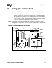
— To mount the three special feet, screw the three
shorter feet onto the existing
screws. See Figure 2-1 for the location of the three special holes.
Warning: Do not remove the nuts from these three holes! This will detach the processor assembly from the
baseboard, and Intel will no longer support the evaluation board.
• The evaluation board is not ATX compatible.
5. Connect desired storage devices to the evaluation board:
The evaluation board supports Primary and Secondary IDE interfaces that can each host one or
two devices (master/slave). When you are using multiple devices, such as a hard disk and a
CD-ROM drive, make sure the hard disk drive has a jumper in the master position and the CD-
ROM has a jumper in the slave position. When you are using a single IDE device with the
evaluation board, be sure that the jumpers set correctly for single master operation. For jumper
settings for other configurations, consult the drive’s documentation.
Note: The evaluation board BIOS only supports hard drives of 16 Gbytes or less.
• Installing the IDE hard disk drive included in your kit:
— Connect the hard drive’s IDE connector to the JP4 connector on the evaluation
board. Be sure to align Pin 1 of the cable connector with pin 1 of JP4.
— Connect the other end to the hard disk drive.
Caution: Make sure the tracer on the ribbon cable is aligned with pin 1 on both the hard disk and the IDE
connector header. Connecting the cable backwards can damage the evaluation board or the hard
disk.
— Connect the hard drive to the power supply.
Note: The hard disk is already formatted and is pre-loaded with the QNX Real-Time Operating System
for Intel Architecture.