


3-4
Celeron™ Processor Development Kit Manual
Theory of Operation
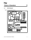
3.2.4 82371EB PCI to ISA/IDE Xcelerator (PIIX4E)
The 82443BX is designed to support the PIIX4E I/O bridge. The PIIX4E is a highly-integrated
multifunctional component that supports the following:
• PCI Revision 2.1 compliant PCI-to-ISA bridge with support for 33 MHz PCI operations
• ACPI Power Management support
• Enhanced DMA controller, interrupt controller and timer functions
• Integrated IDE controller with Ultra DMA/33 support
• USB host interface with support for two USB ports
• System Management Bus (SMB) with support for DIMM Serial Presence Detect
3.2.5 DRAM
The evaluation board provides two 168-pin DIMM module connectors. The DRAM interface is a
64-bit data path that supports Synchronous DRAM (SDRAM). The DRAM interface supports
4 Mbytes to 256 Mbytes of 4-Mbit, 16-Mbit and 64-Mbit DRAM and SRAM technology (both
symmetrical and asymmetrical). Parity is not supported. One 32-Mbyte SDRAM DIMM is
included in the kit.
3.2.6 Power
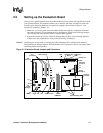
The evaluation board uses an industry standard ATX-style power supply with a 20-pin connector. A
230-watt (minimum) supply is recommended. Note that the ATX power connector is keyed to
prevent incorrect insertion. See “ATX Power Connector” on page 4-3 for a detailed description of
the power connector.
Make sure that the ATX power supply is not plugged into the wall when connecting or
disconnecting it from the evaluation board.
3.2.7 Boot ROM
The system boot ROM installed at U11 is a 2-Mbit 28F002BC flash device. The system is set up
for in-circuit reprogramming of the BIOS, but the flash device is also socketed. This device is
addressable on the XD bus extension of the ISA bus.
3.2.8 RTC/NVRAM
The RTC and NVRAM are contained within the 82371EB PIIX4E device. CMOS NVRAM
backup is provided by a 3-V lithium-ion battery.
3.2.9 Legacy I/O
Support for legacy I/O functions is provided by the Intel 82371EB PIIX4E and the SMC
FDC37B78X SuperI/O* device.