Celeron™ Processor Development Kit Manual
C-1
Schematics C
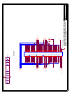
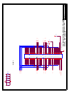
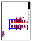
The most current schematics, including “flat” schematics (without the 400-pin connector), are
located on Intel’s Developer Web site at: http://www.intel.com/design/intarch/schems/.
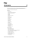
Schematics are provided for the following items:
Baseboard:
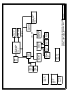
• Block Diagram
• Mini-PCI Connector (Not Populated)
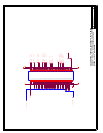
• Processor Assembly Connector
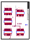
• DIMM0
• DIMM1
• DIMM2 (Not Populated)
• Clocks
• ISA/PCI Pullups
• PCI Slots 0 & 1
• PCI Slot 2
• AGP Connector
• PIIX4 Part 1
• PIIX4 Part 2
• IDE Connectors
• Super I/O
• USB Connectors
• ISA Connectors
• COMx, DB25, Floppy
• BIOS/ Port 80
• ATX Power Connector
• Unused Gates
Processor Assembly:
• Socket 370A Host Interface
• Socket 370B Power Supply
• GTL+ Termination Resistors - Bridge System/Controller
• GTL+ Termination Resistors - Processor
• 82443BX - Bus Interface
• 82443BX - Memory Interface
• Connector Hardware
• ITP/Bus Ratio/Thermal Sensor
• Voltage Regulator


