


Celeron™ Processor Development Kit Manual
4-3
Hardware Reference
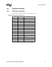
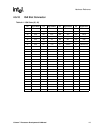
4.5 Connector Pinouts
4.5.1 ATX Power Connector
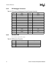
Table 4-2 shows the signals assigned to the ATX style power connector.
Table 4-2. Primary Power Connector (J11)
Pin Name Function
1 3.3 V 3.3 V
2 3.3 V 3.3 V
3 GND Ground
4 +5V +5 V VCC
5 GND Ground
6 +5V +5 V VCC
7 GND Ground
8 PWRGD Power Good
9 5VSB Standby 5 V
10 +12 V +12 V
11 3.3 V 3.3 V
12 –12 V –12 V
13 GND Ground
14 PS_ON# Soft-off control
15 GND Ground
16 GND Ground
17 GND Ground
18 –5 V –5 Volts
19 +5 V +5 V VCC
20 +5 V +5 V VCC