


4-6
Celeron™ Processor Development Kit Manual
Hardware Reference
4.5.6 Serial Ports
COM1 is the top connector. COM2 is the bottom connector.
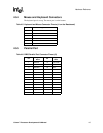
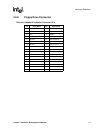
4.5.7 IDE Connector
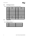
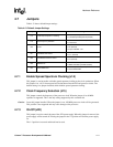
Table 4-7. Serial Port Connector Pinout (J4)
Pin Signal Name
1 DCD
2 Serial In (SIN)
3 Serial Out (SOUT)
4DTR
5GND
6DSR
7RTS
8CTS
9RI
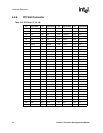
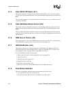
Table 4-8. PCI IDE1 (JP3) and IDE2 (JP4) Connector
Pin Signal Name Pin Signal Name
1 Reset IDE 2 Ground
3 Host Data 7 4 Host Data 8
5 Host Data 6 6 Host Data 9
7 Host Data 5 8 Host Data 10
9 Host Data 4 10 Host Data 11
11 Host Data 3 12 Host Data 12
13 Host Data 2 14 Host Data 13
15 Host Data 1 16 Host Data 14
17 Host Data 0 18 Host Data 15
19 Ground 20 Key
21 DRQ3 22 Ground
23 I/O Write# 24 Ground
25 I/O Read# 26 Ground
27 IOCHRDY 28 BALE
29 DACK3# 30 Ground
31 IRQ14 32 IOCS16#
33 Addr 1 34 Ground
35 Addr 0 36 Addr 2
37 Chip Select 0# 38 Chip Select 1#
39 Activity 40 Ground