


Celeron™ Processor Development Kit Manual
v
5.10.1 Console Redirection ..........................................................................5-9
5.10.2 CE-Ready Windows CE Loader ......................................................5-10
5.10.3 Integrated BIOS Debugger..............................................................5-10
5.11 Embedded BIOS POST Codes ........................................................................5-12
5.12 Embedded BIOS Beep Codes..........................................................................5-15
A PLD Code Listing ................................................................................................... A-1
B Bill of Materials ....................................................................................................... B-1
C Schematics ............................................................................................................... C-1
Index .................................................................................................................................Index-1
Figures
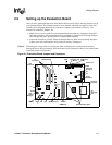
2-1 Evaluation Board Jumpers and Connectors.......................................................2-5
3-1 Evaluation Board Block Diagram........................................................................3-1
5-1 BIOS POST Pre-Boot Environment....................................................................5-2
5-2 Embedded BIOS Setup Screen Menu................................................................5-3
5-3 Embedded BIOS Basic Setup Screen................................................................5-4
5-4 Embedded BIOS Custom Setup Screen ............................................................5-7
5-5 Embedded BIOS Shadow Setup Screen............................................................5-7
5-6 Standard Diagnostic Routines Setup Screen.....................................................5-8
5-7 Start RS232 Manufacturing Link Setup Screen..................................................5-9
5-8 CE-Ready Boot Feature...................................................................................5-10
5-9 Integrated BIOS Debugger Running Over a Remote Terminal ........................5-11
Tables
1-1 Related Documents............................................................................................1-4
3-1 Interrupts ............................................................................................................3-6
3-2 Memory Map ......................................................................................................3-7
4-1 PCI Device Mapping...........................................................................................4-2
4-2 Primary Power Connector (J11) .........................................................................4-3
4-3 ITP Connector Pin Assignment (J2 on the Processor Assembly) ......................4-4
4-4 USB Connector Pinout (J2)................................................................................4-4
4-5 Keyboard and Mouse Connector Pinouts (J1 on the Baseboard)......................4-5
4-6 DB25 Parallel Port Connector Pinout (J3)..........................................................4-5
4-7 Serial Port Connector Pinout (J4).......................................................................4-6
4-8 PCI IDE1 (JP3) and IDE2 (JP4) Connector........................................................4-6
4-9 Diskette Drive Header Connector (JP1).............................................................4-7
4-10 PCI Slots (J7, J8, J9)..........................................................................................4-8
4-11 ISA Slots (J5, J6)................................................................................................4-9
4-12 AGP Slot (J13) .................................................................................................4-10
4-13 Default Jumper Settings...................................................................................4-11
5-1 IDE0-IDE3 Drive Assignments ...........................................................................5-5
B-1 Baseboard Bill of Materials................................................................................ B-1
B-2 Celeron™ Processor Assembly Bill of Materials............................................... B-5