


Celeron™ Processor Development Kit Manual
5-5
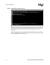
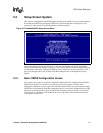
BIOS Quick Reference
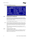
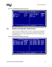
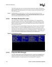
5.3.3 Configuring IDE Drive Types
If true IDE disk file systems (and not their emulators, such as ROM, RAM, or flash disks) are
mapped to drive letters, then the IDE drives themselves must be configured in this section. The
following table shows the drive assignments for Ide0-Ide3:
To use the primary master IDE drive in your system (the typical case), just configure Ide0 in this
section, and map Ide0 to drive C: in the Configuring Drive Assignments section.
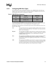
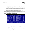
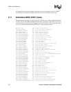
The IDE Drive Types section lets you select the type for each of the four IDE drives: None, User,
Physical, LBA, or CHS.
User This type allows the user to select the maximum cylinders, heads, and sectors
per track associated with the IDE drive. This method is now rarely used since
LBA is now in common use.
Physical This type instructs the BIOS to query the drive’s geometry from the controller
on each POST. No translation on the drive’s geometry is performed, so this type
is limited to drives of 512 Mbytes or less. Commonly, this is used with
embedded ATA PC Cards.
LBA This type instructs the BIOS to query the drive’s geometry from the controller
on each POST, but then translate the geometry according to the industry-
standard LBA convention. This supports up to 16-Gbyte drives. Use this method
for all new drives.
CHS This type instructs the BIOS to query the drive’s geometry from the controller
on each POST, but then translate the geometry according to the Phoenix CHS
convention. Using this type on a drive previously formatted with LBA or
Physical geometry might show data as being missing or corrupted.
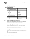
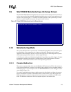
Table 5-1. IDE0-IDE3 Drive Assignments
File System Name Controller Master/Slave
Ide0 Primary (1f0h) Master
Ide1 Primary (1f0h) Slave
Ide2 Secondary (170h) Master
Ide3 Secondary (170h) Slave