


5-4
Celeron™ Processor Development Kit Manual
BIOS Quick Reference
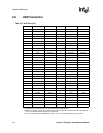
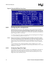
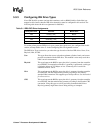
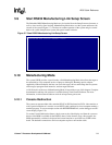
5.3.2 Configuring Drive Assignments
Embedded BIOS allows the user to map a different file system to each drive letter. The BIOS
allows file systems for each floppy (Floppy0 and Floppy1), each IDE drive (Ide0, Ide1, Ide2, and
Ide3), and memory disks when configured (Flash0, ROM0, RAM0, etc.) Figure 5-3 shows how the
first floppy drive (Floppy0) is assigned to drive A: in the system, and then how the first IDE drive
(Ide0) is assigned to drive C: in the system.
To switch two floppy disks around or two hard disks around, just map Floppy0 to B: and Floppy1
to A:, and for hard disks map Ide0 to D: and Ide1 to C:.
Caution: Take care to not skip drive A: when making floppy disk assignments, as well as drive C: when
making hard disk assignments. The first floppy should be A:, and the first hard drive should be C:.
Also, do not assign the same file system to more than one drive letter. Thus, Floppy0 should not be
used for both A: and B:. The BIOS permits this to allow embedded devices to alias drives, but
desktop operating systems may not be able to maintain cache coherency with such a mapping in
place.
A special field in this section entitled “Boot Method: (Windows CE/Boot Sector)” is used to
configure the CE Ready feature of the BIOS. For normal booting (DOS, Windows NT, etc.), select
“Boot Sector” or “Unused”.
5.3.2.1 Configuring Floppy Drive Types
If true floppy drive file systems (and not their emulators, such as ROM, RAM, or flash disks) are
mapped to drive letters, then the floppy drives themselves must be configured in this section.
Floppy0 refers to the first floppy disk drive on the drive ribbon cable (normally drive A:), and
Floppy1 refers to the second drive (drive B:).
Figure 5-3. Embedded BIOS Basic Setup Screen