


Celeron™ Processor Development Kit Manual
2-5
Getting Started
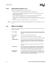
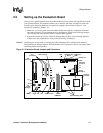
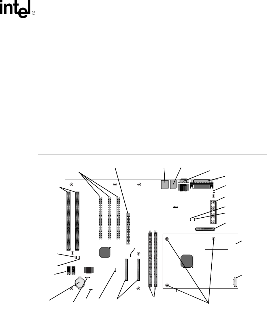
2.5 Setting up the Evaluation Board
Once you have gathered the hardware described in the last section, follow the steps below to set up
your evaluation board. This manual assumes you are familiar with basic concepts involved with
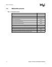
installing and configuring hardware for a personal computer system. Refer to Figure 2-1 for
locations of connectors, jumpers, etc.
1. Make sure you are in a static-free environment before removing any components from their
anti-static packaging. The evaluation board is susceptible to electro-static discharge damage;
such damage may cause product failure or unpredictable operation.
2. Inspect the contents of your kit. Check for damage that may have occurred during shipment.
Contact your sales representative if any items are missing or damaged.
Caution: Connecting the wrong cable or reversing the cable can damage the evaluation board and may
damage the device being connected. Since the board is not in a protective chassis, use caution when
connecting cables to this product.
Figure 2-1. Evaluation Board Jumpers and Connectors
J12
J12
U12 U13
U11
JP1
J21 J22
J23
J14 J15
J12
JP2 JP3
IDE2 IDE1
J20
J24
JP2
D1
D2
J2
J1
J4
J3
J5 J6
J13
J18J17
J11
J7 J8 J9
J2
ISA
PCI AGP Connector USB Keyboard (Top) COM1 (Top)/
Parallel Port
ATX Power
IDE Connectors
Floppy
J14
J15
J20
J21
J22
J23J24 SDRAM
Connectors
Connectors
Connector
/Mouse COM2
Connector
DIMM Slots
ITP
Special Mounting Holes
LEDs
Battery JP2
Post
Code
Debugger
Debugger
Port
Processor
Assembly