


Reference Manual
00809-0100-4663, Rev BA
January 2010
Rosemount 8732
2-6
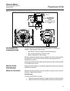
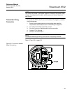
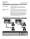
Conduit Cables Run the appropriate size cable through the conduit connections in your
magnetic flowmeter system. Run the power cable from the power source to
the transmitter. Do not run power cables and output signal cables in the same
conduit. For remote mount installations, run the coil drive and electrode
cables between the flowmeter and transmitter. Refer to Electrical
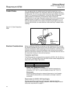
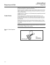
Considerations for wire type. Prepare the ends of the coil drive and electrode
cables as shown in Figure 2-3. Limit the unshielded wire length to 1-in. on
both the electrode and coil drive cables. Excessive lead length or failure to
connect cable shields can create electrical noise resulting in unstable meter
readings.
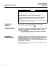
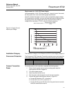
Figure 2-3. Cable Preparation
Detail
Electrical Considerations Before making any electrical connections to the Rosemount 8732, consider
the following standards and be sure to have the proper power supply, conduit,
and other accessories. When preparing all wire connections, remove only the
insulation required to fit the wire completely under the terminal connection.
Removal of excessive insulation may result in an unwanted electrical short to
the transmitter housing or other wire connections.
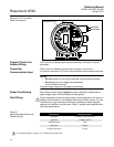
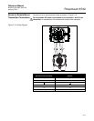
Transmitter Input Power
The 8732 transmitter is designed to be powered by 90-250 V AC, 50–60 Hz or
12–42 V DC. The eighth digit in the transmitter model number designates the
appropriate power supply requirement.
Supply Wire Temperature Rating
Use 12 to 18 AWG wire. For connections in ambient temperatures
exceeding 140 °F (60 °C), use wire rated to at least 194 °F (90 °C).
Disconnects
Connect the device through an external disconnect or circuit breaker.
Clearly label the disconnect or circuit breaker and locate it near the
transmitter.
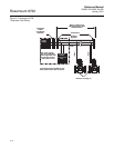
Requirements for 90-250 V AC Power Supply
Wire the transmitter according to national, local, and plant electrical
requirements for the supply voltage. In addition, follow the supply wire and
disconnect requirements on page 2-7.
NOTE
Dimensions are in
inches
(millimeters).
1.00
(26)
Cable Shield
Model Number Power Supply Requirement
1 90-250 V AC
2 12-42 V DC