


Reference Manual
00809-0100-4663, Rev BA
January 2010
Rosemount 8732
G-2
PARAMETERS AND
DESCRIPTIONS
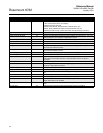
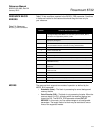
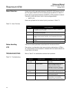
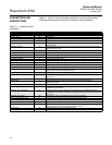
Table G-1 lists all of the configurable parameters of the transducer block,
indicating the descriptions and index numbers for each parameters.
Table G-1. Transducer Block
Parameters
Parameter Index Number Definition
ALERT_KEY 4 ID number of the transmitter–may be used on the host for sorting alarms
BLOCK_ALM 8 Block alarm
COIL_DRIVE_FREQ 35 Frequency at which the coils are being driven (5 or 37.5 Hz)
DAMPING 30 Damping filter value (in seconds)
DENSITY_UNIT 31 Unit code associated with DENSITY_VALUE. Valid values are lb/cubic feet, or
kg/cubic meter
DENSITY_VALUE 75 User entered density value to be used by the transducer block when calculating flow
rate in mass flow units
DIAGNOSTIC_HANDLING 60 On/Off handling for diagnostics
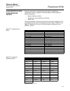
ELECTRODE_MATERIAL 51 Enumerated string indicating flange material of installed flowtube
ELECTRODE_TYPE 52 Enumerated string indicating electrode type of installed flowtube
EP_TRIG_COUNTS 40 Number of EP measurements that must be above the trigger level to set empty pipe
EP_TRIG_LEVELS 41 Empty Pipe Trigger Levels
FLANGE_MATERIAL 54 Enumerated string indicating liner material of installed flowtube
FLANGE_TYPE 53 Enumerated string indicating liner material of installed flowtube
FLOW_TUBE_SERIAL_NUMBER 49 Flow tube serial number from physical tag on flowtube
FLOW_TUBE_TAG 48 Text String Identifier of flowtube
LICENSE_KEY 78 Key/password to enable diagnostic features. Any changes to the licensing will be
shown in the LICENSE_STATUS parameter
LINER_MATERIAL 50 Enumerated string indicating liner material of installed flowtube
LOI_LANG 39 Selects the language to be used in the local display for status and diagnostics
messages
LOW_FLOW_CUTOFF 37 When flow rate is less than this entered value, flow rate output will be set to 0 ft/s
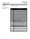
MODE_BLK 5 Mode of the record of the block–contains the actual, target, permitted,
and normal modes
SENSOR_CAL_DATE 25 Date of the last sensor calibration–intended to reflect the calibration of the sensor
SENSOR_CAL_LOC 24 Location of the last sensor calibration–describes the physical location at which the
calibration was performed
SENSOR_CAL_METHOD 23 Method of the last sensor calibration–ISO defines several standard methods of
calibration (This parameter is intended to record that method or if some other method
was used.)
SENSOR_CAL_WHO 26 Name of the person responsible for the last sensor calibration
STATUS_MESSAGE_MFG 61 Used by manufacturing to test groups to simulate status codes
STRATEGY 3 Can be used to help group the blocks (Not checked or processed by the block)
TAG_DESC 2 Static tag–ASCII character string
TUBE_CAL_NO 33 Sensor gain and zero offset number used in flow calculation
(Number entered is locate on physical tag of the sensor.)
TUBE_SIZE 34 Tube Size. See Tube Size for actual line sizes
UPDATE_EVT 7 Update event