


Reference Manual
00809-0100-4663, Rev BA
January 2010
2-5
Rosemount 8732
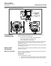
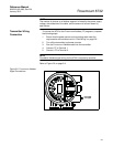
1. Disconnect power to the transmitter.
2. Remove electronics cover.
3. Remove display if applicable.
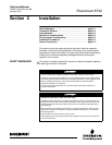
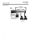
4. Identify the location of each switch (see Figure 2-2).
5. Change the setting of the desired switches with a small screwdriver.
6. Replace the electronics cover.
Figure 2-2. Rosemount 8732
Electronics Board and Hardware
Switches
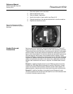
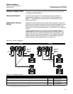
Conduit Ports and
Connections
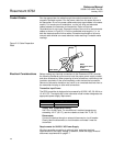
Both the sensor and transmitter junction boxes have ports for
1
/2-inch NPT
conduit connections, with optional CM20 and PG 13.5 connections available.
These connections should be made in accordance with national, local or plant
electrical codes. Unused ports should be sealed with metal plugs and PTFE
tape or other thread sealant. Connections should also be made in accordance
with area approval requirements, see examples below for details. Proper
electrical installation is necessary to prevent errors due to electrical noise and
interference. Separate conduits are not necessary for the coil drive and signal
cables connecting the transmitter to the sensor, but a dedicated conduit line
between each transmitter and sensor is required. A shielded cable must be
used.
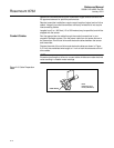
Example 1: Installing flanged sensors into an IP68 area. Sensors must be
installed with IP68 cable glands and cable to maintain IP68 rating. Unused
conduit connections must be properly sealed to prevent water ingress. For
added protection, dielectric gel can be used to pot the sensor terminal block.
Example 2: Installing flowmeters into explosion proof/flameproof areas.
Conduit connections and conduit must be rated for use in the hazardous area
to maintain flowmeter approval rating.