


Reference Manual
00809-0100-4663, Rev BA
January 2010
G-3
Rosemount 8732
FLOW-SPECIFIC BLOCK
CONFIGURATION
VALUES
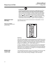
Once the transmitter is installed and communication is established,
configuration must be completed. Three parameters must be entered for
proper configuration:
• Sensor calibration number
• Engineering units (configured via AI block)
• Sensor size
The sensor calibration number can be found on the sensor nameplate. A list
of all possible sensor sizes and engineering units are listed in Table G-2 and
Table G-3. Mass units (lb, kg, ton, and ston) require configuration of the
DENSITY_VALUE.
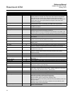
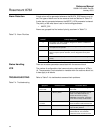
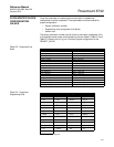
Table G-2. Supported Line
Sizes
Table G-3. Supported
Engineering Units
User-Defined Sensor Line Size
0.1 in. (3 mm) 16 in. (400 mm)
0.15 in. (4 mm) 18 in. (450 mm)
0.25 in. (6 mm) 20 in. (500 mm)
0.3 in (8 mm) 24 in. (600 mm)
0.5 in. (15 mm) 28 in. (700 mm)
0.75 in. (20 mm) 30 in. (750 mm)
1 in. (25 mm) 32 in (800 mm)
1.5 in. (40 mm) 36 in. (900 mm)
2 in. (50 mm) 40 in. (1000 mm)
2.5 in. (65 mm) 42 in. (1050 mm)
3 in. (80 mm)
(1)
(1) Default Factory Configuration
48 in. (1200 mm)
4 in. (100 mm) 54 in. (1350 mm)
6 in. (150 mm) 56 in. (1400 mm)
8 in. (200 mm) 60 in. (1500 mm)
10 in. (250 mm) 64 in. (1600 mm)
12 in. (300 mm) 72 in. (1800 mm)
14 in. (350 mm) 80 in. (2000 mm)
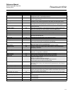
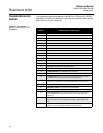
User Defined Engineering Units
• ft/s
(1)
(1) Default factory configuration
•CFS •bbl/s •kg/s
•ft/m •CFM •bbl/min •kg/min
• ft/h •CFH •bbl/h •kg/h
•m/s •ft
3
/d • bbl/d • kg/d
•m/h •m
3
/s •cm
3
/s • STon/s
• gal/s • m
3
/min • cm
3
/min • STon/min
•GPM •m
3
/h •cm
3
/h • STon/h
• gal/h • m
3
/d • cm
3
/d • STon/d
• gal/d •IGAL/s •lb/s • t/s
• L/s • IGAL/min • lb/min • t/min
•L/min •IGAL/h •lb/h • t/h
• L/h • IGAL/d • lb/d • t/d
•L/d