


99
F
W
D
W
H
E
E
L
C
H
A
I
R
S
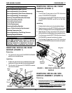
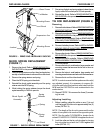
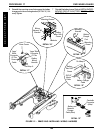
REMOVING/INSTALLING WIRING
HARNESS (FIGURE 12)
Removing
1. Remove the battery boxes. Refer to
INSTALLING/RE-
MOVING GROUP 24 BATTERY BOXES in PRO-
CEDURE 9 of this manual.
2. Remove the two (2) mounting screws that secure
the battery charger port to the mounting bracket and
remove the battery charger port (DETAIL A).
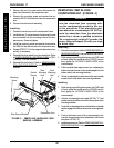
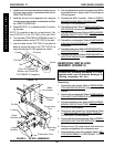
3. Remove the two (2) mounting screws and locknuts
that secure the wiring harness w/bracket to the battery
box sub-frame (DETAIL B).
4. Cut tie-wrap A, which secures the Lego block
connectors to the base frame (DETAIL C).
5. Disconnect the Lego block connector of the bat-
tery wiring harness from the Lego block connec-
tor of the sensor cable assembly (DETAIL C).
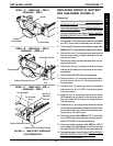
6. Cut tie-wrap B, which secures the battery charger
cable and the RIGHT motor cable to the battery
box sub-frame (DETAIL D).
7. Disconnect the battery harness/charger cable
(BLUE) from the controller connector (BLUE)
(DETAILE).
8. Remove the wiring harness.
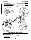
Installing
1. Connect the battery harness/charger cable (BLUE)
to the controller connector (BLUE) (DETAILE).
2. Connect the Lego block connector of the battery wir-
ing harness to the Lego block connector of the sen-
sor cable assembly (DETAIL C).
3. Secure the Lego block connectors to the base frame
with a NEW tie wrap (DETAIL C).
4. Install the two (2) mounting screws and locknuts that
secure the wiring harness w/bracket to the battery
box sub-frame. Use Loctite 242 and torque mounting
screws to 160-inch pounds (DETAIL B).
5. Secure the battery charger cable and the RIGHT mo-
tor cable to the battery box sub-frame with a NEW tie
wrap (DETAIL D).
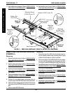
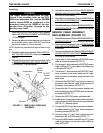
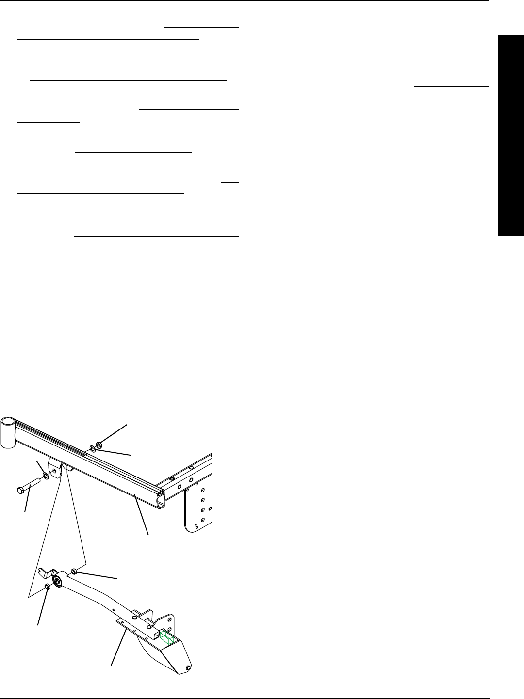
Base
Frame
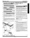
FIGURE 11 - REPLACING THE SUSPENSION ARM
Locknut
Suspension Arm
Spacer
Mounting
Screw
Spacer
WasherWasher
FWD WHEELCHAIRS PROCEDURE 17
3. Remove the battery boxes. Refer to INSTALLING/RE-
MOVING GROUP 24 BATTERY BOXES in PRO-
CEDURE 9 of this manual.
4. Remove the drive wheel from the wheelchair. Refer
to
REMOVING/INSTALLING DRIVE WHEELS in
PROCEDURE 12 of this manual.
5. Remove the shock. Refer to
REMOVING/INSTALL-
ING SHOCKS in this procedure of this manual.
6. Remove the tie rods from the EXISTING suspension
arm. Refer to
TIE ROD REPLACEMENT in this pro-
cedure of the manual.
7. Remove the side shroud assembly. Refer to
RE-
PLACING SIDE SHROUD ASSEMBLY in this proce-
dure of the manual.
8. Remove the gearbox from the EXISTING suspension
arm. Refer to
REMOVING/INSTALLING GEARBOX
in this procedure of the manual.
9. Remove the locknut, two (2) spacers, two (2) wash-
ers and the mounting screw that secures the EXIST-
ING suspension arm to the base frame.
10. Remove EXISTING suspension arm from the base
frame.
11. Secure the NEW suspension arm to the base frame
using the mounting screw, two (2) washers, two (2)
spacers and the locknut. Torque the locknuts to 85
-inch pounds.
12. Reassemble the wheelchair by reversing STEPS 1-8.