


34
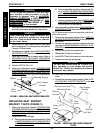
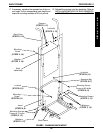
BASE FRAMEPROCEDURE 7
B
A
S
E
F
R
A
M
E
B. Remove adjustable seat frame subassembly. Re-
fer to
INSTALLING/REMOVING ADJUSTABLE
SEAT FRAME ASSEMBLY AND OR COMPO-
NENT REPLACEMENT in PROCEDURE 6 of
this manual.
C. Remove captains van seat. Refer to I
NSTALLING/
REMOVING CAPTAINS VAN SEAT ASSEMBLY in
PROCEDURE 6 of this manual.
3. Remove the seat mount plates. Refer to
REPLACING SEAT
MOUNTING PLATES in this procedure of the manual.
NOTE: Before removing seat mounting plates, note the po-
sition of the washers.
4. Remove the seat support brackets. Refer to
REPLAC-
ING SEAT SUPPORT BRACKETS in this procedure of
the manual.
5. Remove the seat stop screw that is closest to the end
cap. Refer to REMOVING/INSTALLING SEAT STOP
SCREWS in this procedure of the manual.
6. Remove the end cap and channel cover.
7. Slide existing T-Nut(s) out of channel.
8. Insert NEW T-Nut(s) into channel in correct orientation.
9. Replace channel cover and end cap.
WARNING
The seat stop screws must be in place be-
fore operation of your power wheelchair.
Ensure the T-Nut(s) are positioned between
both seat stop screws.
10. Use Loctite 242
and reinstall seat stop screw into base
frame.
11. Reinstall the seat seat support brackets. Refer to
RE-
PLACING SEAT SUPPORT BRACKETS in this pro-
cedure of the manual.
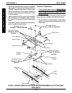
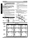
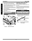
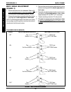
FIGURE 2 - REPLACING SEAT SUPPORT BRACKETS
Washer
Seat Support
Bracket
Base
Frame
Mounting Screws
T-Nut
WARNING
Do not adjust the position of the seat sup-
port bracket in this procedure. If an ad-
justment is desired, refer to
ADJUSTING
WEIGHT DISTRIBUTION in PROCEDURE 15 -
MWD WHEELCHAIRS, PROCEDURE 16 - RWD
WHEELCHAIRS, or PROCEDURE 17 - FWD
WHEELCHAIRS of this manual.
4. Remove the two (2) mounting screws and washers that
secure the seat support bracket to the base frame.
WARNING
When installing seat support bracket, en-
sure the mounting screws are threaded
into the T-Nuts located inside the channel
of the base frame.
5. Secure the NEW seat support bracket to base frame
with the existing two (2) mounting screws and washers.
Torque to 156-inch pounds.
6. Reinstall seat mount plates. Refer to
REPLACING SEAT
MOUNTING PLATES in this procedure of the manual.
7. Adjust seat mount plates to desired angle. Refer to
MOUNTING PLATE - SEAT ANGLE ADJUSTMENT
AND INSTALLATION ORIENTATION in PROCEDURE
6 of this manual.
8. Reverse STEP 2A, 2B or 2C.
9. Perform the instructions outlined in
PREPARATIONS
FOR REMOVING/INSTALLING SEAT FRAME (STAN-
DARD FRAME, ADJUSTABLE FRAME, AND CAP-
TAINS VAN SEAT) in PROCEDURE 6 of this manual.
REPLACING SEAT SUPPORT
BRACKET T-NUTS (FIGURE 3)
1. Perform the instructions outlined in PREPARATIONS
FOR REMOVING/INSTALLING SEAT FRAME (STAN-
DARD FRAME, ADJUSTABLE FRAME, AND CAP-
TAINS VAN SEAT) in PROCEDURE 6 of this manual.
2. Perform one (1) of the following:
A. Remove standard seat frame subassembly. Refer
to
REMOVING/INSTALLING STANDARD SEAT
FRAME SUBASSEMBLY in PROCEDURE 6 of
this manual.
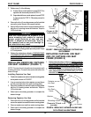
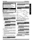
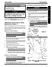
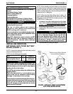
FIGURE 3 - REPLACING SEAT SUPPORT BRACKET
T-NUTS
Channel Cover
Mounting Screw
T-Nut
End Cap
Seat Support
Bracket
Base
Frame
Channel
Stop
Screw
Washer