


96
FWD WHEELCHAIRSPROCEDURE 17
F
W
D
W
H
E
E
L
C
H
A
I
R
S
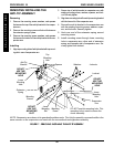
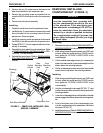
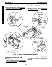
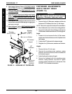
REMOVING/INSTALLING
GEARBOX (FIGURE 9)
CAUTION
Perform the following procedure in a des-
ignated work area to prevent damage to
flooring (carpeting, tile, etc.).
Removing
1. Remove the rear shroud. Refer to
REMOVING/IN-
STALLING REAR SHROUD in this procedure of the
manual.
2. Remove the counterweight. Refer to
REMOVING/IN-
STALLING COUNTERWEIGHT in this procedure of
the manual.
3. Remove the battery boxes. Refer to
INSTALLING/RE-
MOVING GROUP 24 BATTERY BOXES in PRO-
CEDURE 9 of this manual.
4. Remove the drive wheel from the wheelchair. Refer
to
REMOVING/INSTALLING DRIVE WHEELS in
PROCEDURE 12 of this manual.
5. Remove the side shroud assembly. Refer to REMOV-
ING/INSTALLING THE SIDE SHROUD in this proce-
dure of the manual.
6. Remove the six (6) socket screws that secure the
existing motor/gearbox to the suspension arm.
7. Remove existing motor from gearbox. Refer to
MO-
TOR REPLACEMENT in PROCEDURE 12 of this
manual.
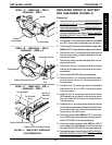
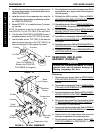
Mounting
Screw
Base
Frame
Locknut
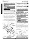
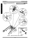
FIGURE 8 - TIE ROD ASSEMBLIES
Small
Washer
Large
Washer
Suspension
Arm
Tie Rod
Suspension Arm
DETAIL “A”
Tie Rod
Collar
(Turn CLOCKWISE To
Shorten And COUNTER-
CLOCKWISE To Lengthen)
Nut
5 inches
Center
Center
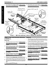
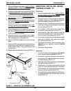
8. Securely tighten the tie rods to the base frame AND to
the suspension arm. Apply Loctite 242 and torque to
360-inch pounds.
9. Reinstall the MKIV controller. Refer to
REMOV-
ING/INSTALLING MKIV CONTROLLER in PRO-
CEDURE 13 of this manual.
10. Reinstall the shocks. Refer to
REMOVING/INSTALL-
ING SHOCKS in this procedure of this manual.
11. Reinstall the battery boxes. Refer to
INSTALLING/RE-
MOVING GROUP 24 BATTERY BOXES in PRO-
CEDURE 9 of this manual.
12. Reinstall the counterweight. Refer to
REMOVING/IN-
STALLING COUNTERWEIGHT in this procedure of
the manual.
13. Reinstall the rear shroud. Refer to
REMOVING/INSTALL-
ING REAR SHROUD in this procedure of the manual.
14. Reinstall the front shroud. Refer to
REMOVING/INSTALL-
ING FRONT SHROUD in this procedure of the manual.
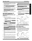
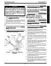
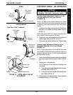
3. Install the tie rod onto the base frame using the mount-
ing screw, large washer, small washer and locknut.
HAND TIGHTEN ONLY.
4. Install the tie rod in the suspension arm using the
mounting screw, large washer, small washer and lock-
nut. HAND TIGHTEN ONLY.
5. Repeat STEPS 1-4 to install the three (3) remain-
ing tie rods.
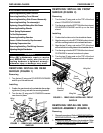
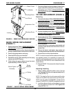
NOTE: To complete proper tie rod adjustment, Per-
form STEPS 6-7 on the TOP TWO (2) tie rods ONLY.
6. Turn the collar COUNTER-CLOCKWISE for one (1)
complete revolution on the TOP TWO (2) tie rods.
7. Lock the collar on the TOP TWO (2) tie rods into
place by turning the nuts on the TOP TWO (2) tie
rods until they are FLUSH against the collars.
Mounting
Screw