


58
PROCEDURE 12 WHEELS/MOTORS
W
H
E
E
L
S
/
M
O
T
O
R
S
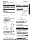
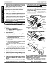
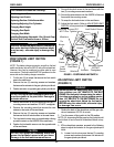
4. Remove the two (2) mounting screws, spacers, and
washers that secure the MKIV controller to the base
frame. Set MKIV controller onto ground/floor.
NOTE: STEPS 5, 6, and 7 are necessary to obtain
easier access to the motor/controller connection.
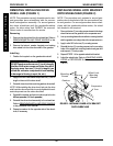
5. Remove the mounting screw and spacer that secure
the top of the shock to the base frame.
6. Loosen, DO NOT remove, the mounting screw that se-
cures the bottom of the shock to the suspension arm.
7. Rotate top of shock toward the inside of the wheelchair.
]
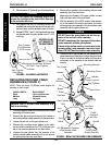
8. Disconnect the motor connector from controller.
9. Remove the two (2) allen screws and washers that
secure the motor to the gearbox.
CAUTION
DO NOT damage the motor/gearbox coupling.
10. Carefully pull the motor away from the gearbox.
Installing
1. Perform one (1) of the following:
A. For RWD and MWD perform STEPS 2-3.
B. For FWD ONLY perform STEPS 2-10.
2. Perform the following:
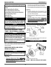
A. Inspect the coupling for wear and damage. If dam-
age is evident, replace coupling.
B. Install coupling onto gearbox input shaft inserting cou-
pling drive plate onto slot on shaft.
C. Carefully align motor and coupling and place motor
against gearbox.
D. With motor against gearbox, turn gearbox drive shaft
until the coupler seats into gearbox.
NOTE: When properly aligned, motor will be seated into
gearbox.
E. Install two (2) allen screws. Use Loctite 242, tighten
allen screws evenly and then torque to 75-inch lbs.
3. Reconnect right and/or left motor connector to controller.
4. Rotate the top of the shock of the shock toward the inside
of the wheelchair.
5. Install the mounting screw and spacer that secure the top
of the shock to the base frame. Torque to 156 - inch
pounds.
6. Tighten the mounting screw that secures the bottom of
the shock to the suspension arm. Torque to 156 - inch
pounds.
7. Install the two mounting screws that secure the MKIV
controller to the base frame. Torque to 156 - inch pounds.
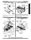
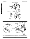
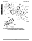
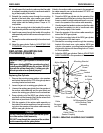
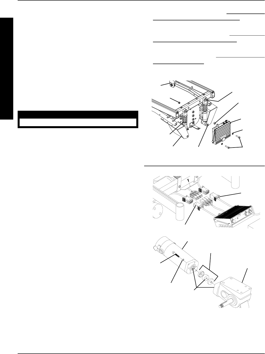
FIGURE 5 - REMOVING/INSTALLING THE MOTOR -
CONVENTIONAL MOTOR/GEARBOX FOR RWD,
MWD AND FWD MODELS
Slots*
*NOTE: The following slot locations must line up for proper
installation: Slots on coupling of motor, the slots on the
coupling and the slots on the gearbox.
Gearbox
Motor
Allen
Screw
Washer
Coupling
Motor Connector
Motor
Connector
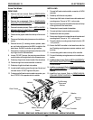
8. Install the battery box(es). Refer to INSTALLING/RE-
MOVING GROUP 24 BATTERY BOXES in PROCE-
DURE 9 of this manual.
9. Install the counterweight. Refer to
REMOVING/IN-
STALLING THE COUNTERWEIGHT in PROCE-
DURE 17 of this manual.
10. Install the front shroud. Refer to
REMOVING/INSTALL-
ING FRONT SHROUD in PROCEDURE 17 of this
manual.
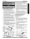
ARROW FWD MODEL ONLY
RWD, MWD, AND ARROW FWD MODELS
Base
Frame
MKIV
Controller
Mounting
Screws
Washer
Shock
Suspension
Arm
Mounting Screw
(REMOVE)
Mounting Screw
(Loosen, DO NOT
REMOVE)
Locknut
Spacer