


102
PROCEDURE 17
F
W
D
W
H
E
E
L
C
H
A
I
R
S
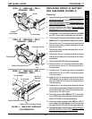
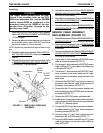
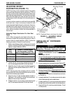
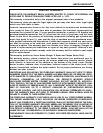
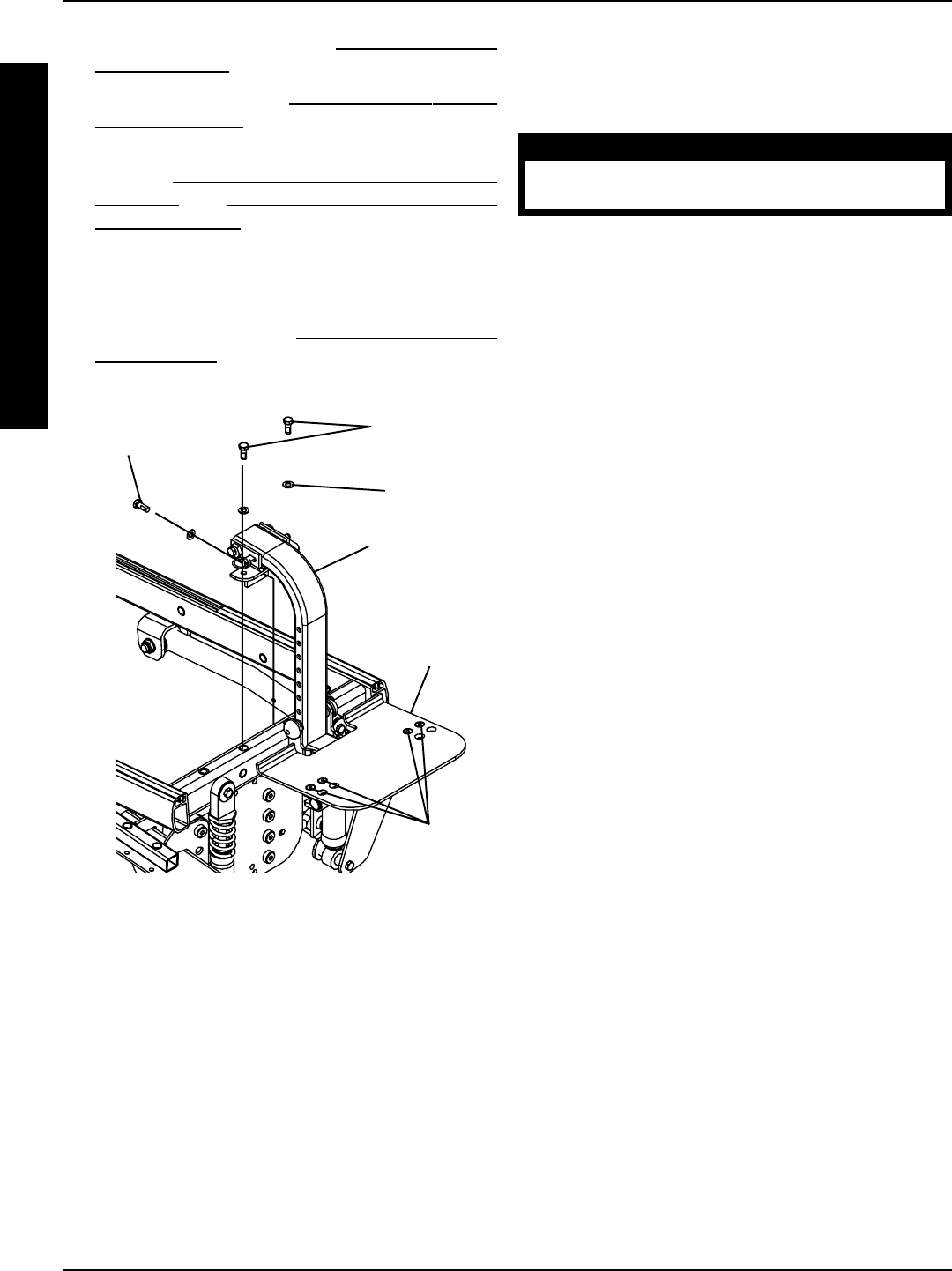
FIGURE 14 - INSTALLING 90
o
FOOTBOARD
Flat Screws
Washers
Locknuts
90
o
Footrest
Support
Mounting
Screws
(STEP 7)
Washer
90
o
Footboard
Mounting
Screw (STEP 6)
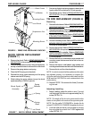
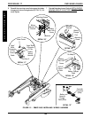
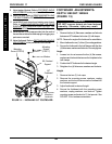
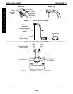
FOOTBOARD ADJUSTMENTS-
DEPTH/HEIGHT/ANGLE
(FIGURE 15)
WARNING
DO NOT remove detent pin from footrest
assembly. Otherwise, injury may result.
Depth
1. Remove the four (4) flat screws, washers and locknuts
that secure 90
o
footboard to the two (2) half clamps.
NOTE: Observe the angle of the footboard for reinstallation.
2. Move
footboard to one (1) of two (2) mounting positions.
3. Secure the footboard to the half clamps with the four
(4) flat screws, washers and locknuts. Securely tighten.
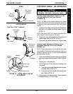
Angle
1. Loosen, but do not remove the four (4) flat screws,
washers and locknuts that secure the footplate to the
half clamps.
2. Position the 90
o
footboard to the desired angle.
3. Retighten four (4) flat screws, washers and locknuts.
Height
1. Remove the two (2) hub caps.
2. Remove the mounting screw, washers, caplug
washers, and locknut that secure the footboard to
the footrest support.
3. Adjust footboard to desired height.
4. Secure the footboard with the mounting screw,
washers, caplug washers, and locknut. Tighten
mounting screw and locknut to 12 foot pounds. See
FIGURE 15 for hardware orientation.
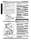
9. Adjust angle of footrest. Refer to
FOOTREST ANGLE
ADJUSTMENTS in this procedure of the Manual.
10. Install the seat. Refer to
REMOVING/INSTALLING
THE SEAT FRAME in PROCEDURE 6 of this manual.
11. Install NEW front shroud and existing rear shroud.
Refer to
REMOVING/INSTALLING THE REAR
SHROUD and REMOVING/INSTALLING THE
FRONT SHROUD in this procedure of the Manual.
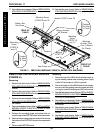
12. Install the two (2) end caps provided into the ends of
the seat frame where the telescoping front rigging sup-
ports were mounted.
13. Adjust footboard. Refer to
DEPTH/HEIGHT/ANGLE
ADJUSTMENT in this procedure of the manual.
FWD WHEELCHAIRS