


38
NOTE: If needing a reference for proper mounting holes
for the back angle required, or if changing the original back
angle, refer to BACK ANGLE ADJUSTMENT in this pro-
cedure of the manual.
WARNING
The back canes MUST be fastened se-
curely to the seat frame BEFORE using the
wheelchair. Torque to 75-inch pounds.
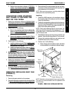
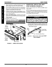
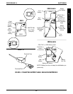
13. Secure the two (2) NEW back canes to the seat frame
with the existing four (4) mounting screws, washers,
spacers, and locknuts. Use Loctite 242 and torque to
75-inch pounds.
14. Secure the top of the existing/new back upholstery to
the back canes with the two (2) existing mounting
screws and washers.
15. Secure bottom of the existing/NEW back upholstery
to rear of the seat pan.
16. Secure the bottom of the existing/NEW back uphol-
stery to the back canes with new tie-wraps.
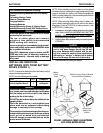
NOTE: Clean upholstery with warm DAMP cloth and mild
detergent to remove superficial soil.
WARNING
Laundering or moisture will reduce flame
retardancy of the upholstery.
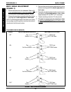
NOTE: When replacing the back upholstery, back as-
sembly or changing back height, follow these guidelines
for spreader bar height (where applicable):
BACK HEIGHT u SPREADER BAR
HEIGHT
16-inches* 5-inches
17-inches* 5-inches
18-19-inches* 7-inches
20-24inches 7-inches
NOTE: Spreader Bar required on back heights 20-24-
inches. *Spreader bar ONLY required on these back
heights if the width or depth of the chair exceeds 19-inches.
u Height of Spreader Bar from Bottom of Back Canes
to Top of Spreader Bar Clamp.
HEAVY DUTY MODELS
NOTE: Spreader bar required on all Heavy Duty models.
BACK HEIGHT u SPREADER BAR
HEIGHT
16-17-inches 5-inches
18-24-inches 7-inches
uHeight of Spreader Bar from Bottom of Back
Canes to Top of Spreader Bar Clamp.
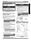
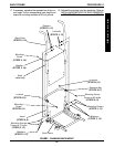
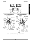
CHANGING BACK HEIGHT
(FIGURE 2)
NOTE: If changing the back height, new back upholstery
may be needed as well. Refer to the following chart to deter-
mine if new back upholstery is needed:
BACK UPHOLSTERY HEIGHT RANGES
16-17-INCHES
18-19-INCHES
20-INCHES
21-22-INCHES
23-24-INCHES
If back height required is within the range of the origi-
nal back height, only new back canes will be needed.
If the back height required is NOT within the range of
the original back height, new back upholstery, as well
as new back canes will be needed.
NOTE: Existing hardware and inserts will be reused.
1. Remove the armrests from the wheelchair. Refer to
IN-
STALLING/REMOVING FLIP BACK ARMRESTS in
PROCEDURE 4 of the owners manual, 1081227.
NOTE: Note the correct mounting screw mounting positions
to ensure the proper back angle for reinstallation.
2. Remove the two (2) mounting screws and washers that
secure the existing back upholstery to the back canes.
3. Remove the four (4) mounting screws, washers, spac-
ers, and locknuts that secure the existing back canes to
the seat frame.
4. Remove the inserts from the existing back canes.
5. Remove the back assembly from the wheelchair.
6. If applicable, loosen, but do not remove the mounting
screws and locknuts that secure the spreader bar to the
existing back canes.
7. Remove existing back canes from the back assembly.
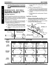
8. Slide the inserts into the bottom of the NEW back canes.
9. Line up the mounting holes of the inserts with the mount-
ing holes in the back canes.
NOTE: To keep the inserts lined up for reinstallation onto the
wheelchair, start one (1) of the mounting screws through the
back cane from inside of the wheelchair to hold the insert in
place.
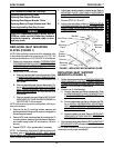
10. Slide the NEW back canes through the existing/NEW
back upholstery and spreader bar.
11. If applicable, loosely tighten the mounting screws that
secure the spreader bar to the NEW back canes.
12. Line up the mounting holes in the back canes with the
mounting holes in the seat frame.
BACK FRAMEPROCEDURE 8
B
A
C
K
F
R
A
M
E