


88
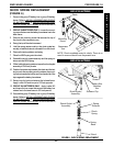
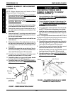
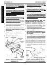
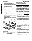
Suspension Arm Hex Screw
(1/2 x 7-inches)
FIGURE 15 - REPLACING SUSPENSION ARM FOR
WHEELCHAIRS WITH MOTOR/GEARBOX ASSEMBLY
Suspension Arm
Plug
Button
Beveled
Washers
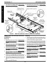
REPLACING SUSPENSION ARM FOR
WHEELCHAIRS WITH MOTOR/
GEARBOX ASSEMBLY (FIGURE 15)
1. Remove the drive wheels from the wheelchair. Refer to
REMOVING/INSTALLING DRIVE WHEELS in PROCE-
DURE 12 of this manual.
2. Loosen the hex screws that secure wiring harness to
sub-frame assembly.
3. Remove gearbox from the existing suspension arm. Re-
fer to
REMOVING/INSTALLING GEARBOX in this proce-
dure of the manual.
4. Remove plug buttons from the middle of the base frame.
5. Remove the hex screws and the beveled washers that
secure the suspension arm assembly to the base frame.
6. Remove existing suspension arm from the wheelchair.
NOTE: When installing the NEW suspension arm, the
beveled washers MUST be placed on the inside and out-
side of the base frame, with the bevels facing each other.
7. Install the NEW suspension arm assembly onto the
base frame.
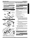
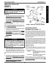
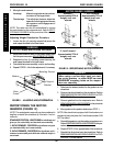
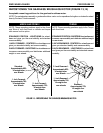
1. Determine the desired mounting position of the gear-
less/brushless motor. Refer to
ACCEPTABLE
MOUNTING POSITIONS FOR THE GEARLESS/
BRUSHLESS MOTOR in this procedure of the
manual.
2. Remove the group 22 battery box or group 24 battery
boxes. Refer to
INSTALLING/REMOVING BATTERY
BOX - GROUP 22 BATTERY BASE FRAMES or IN-
STALLING/REMOVING BATTERY BOXES - GROUP
24 BATTERY BASE FRAMES in PROCEDURE 9 of
this manual.
3. If necessary, remove the battery box tray. Refer to
RE-
MOVING THE BATTERY BOX TRAY in this proce-
dure of the manual.
4. Remove the drive wheel from the wheelchair. Refer to
REMOVING/INSTALLING DRIVE WHEELS in PROCE-
DURE 12 of this manual.
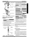
5. Loosen the adjustment screw that secures the motor
release handle to the brake release shaft.
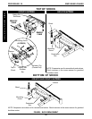
6. Remove the four (4) mounting screws and washers
that secure the motor to the suspension arm.
7. Slide the motor forward or backward to the desired
mounting position.
8. Secure the motor to the mounting position determined
in STEP 1 and secure with the four (4) existing mount-
ing screws and washers. Torque to 13 foot/pounds.
9. Securely tighten adjustment screw.
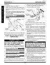
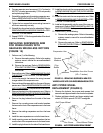
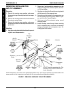
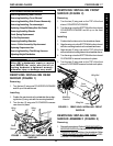
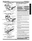
FIGURE 14 - REPOSITIONING THE GEARLESS/
BRUSHLESS MOTOR
10. Reinstall the drive wheel to the wheelchair. Refer to
RE-
MOVING/INSTALLING DRIVE WHEELS in PROCE-
DURE 12 of this manual.
11. Repeat STEPS 1-9 for opposite side of wheelchair.
12. If necessary, reinstall the battery box tray. Refer to
RE-
MOVING THE BATTERY BOX TRAY in this proce-
dure of the manual.
13. Remove the group 22 battery box or group 24 battery
boxes. Refer to
INSTALLING/REMOVING BATTERY
BOX - GROUP 22 BATTERY BASE FRAMES or IN-
STALLING/REMOVING BATTERY BOXES - GROUP
24 BATTERY BASE FRAMES in PROCEDURE 9 of
this manual.
Motor Release
Lever
Brake Release
Shaft
Adjustment
Screw
Mounting
Screws
Washer
Suspension Arm
Motor
RWD WHEELCHAIRSPROCEDURE 16
R
W
D
W
H
E
E
L
C
H
A
I
R
S