


55
W
H
E
E
L
S
/
M
O
T
O
R
S
This Procedure includes the following:
Replacing Pneumatic Tires/Tubes - Drive Wheels/
Casters
Removing/Installing Drive Wheels
Removing/Installing Drive Wheel Hub
Installing Wheel Lock Bracket onto Wheelchair
Removing/Installing Casters
Replacing Forks
Motor Replacement
WARNING
After ANY adjustments, repair or service and BEFORE
use, make sure all attaching hardware is tightened
securely - otherwise injury or damage may result.
CAUTION
As with any vehicle, the wheels and tires should
be checked periodically for cracks and wear
and should be replaced.
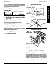
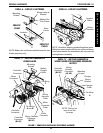
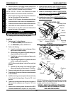
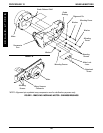
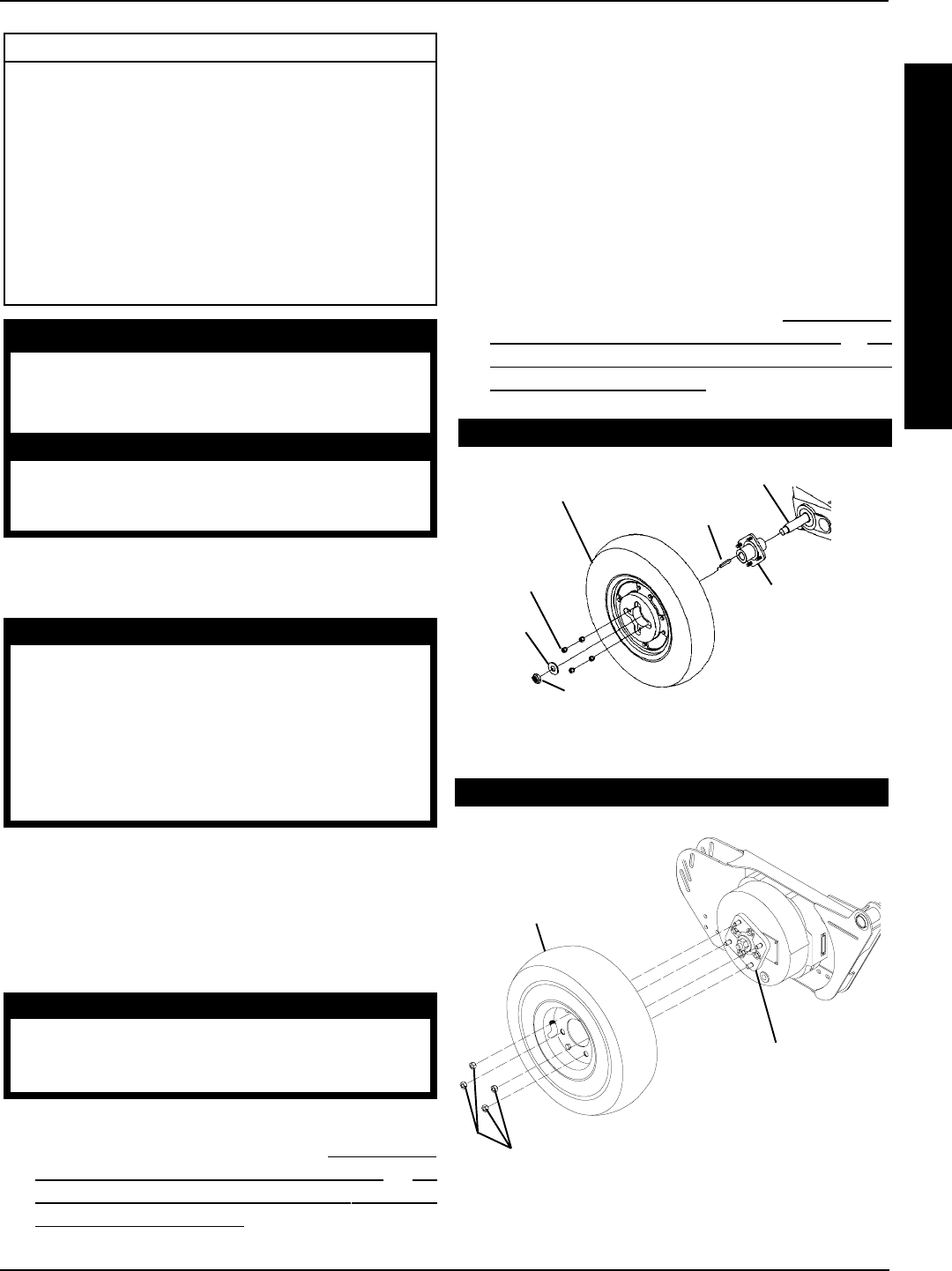
Keystock
*Locknut
*Washer
Four (4)
Beveled
Hex Nuts
Drive Wheel Assembly
Wheel Hub
Assembly
Gearbox Drive Shaft
FIGURE 1 - REMOVING/INSTALLING DRIVE WHEELS
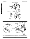
2. Remove the four (4) beveled hex nuts that secure the
drive wheel assembly to the wheel hub assembly.
3. Remove existing drive wheel assembly from wheel hub.
Installing
1. Reinstall new/existing drive wheel assembly to the
wheel hub assembly and torque the four (4) beveled
hex nuts to 160-inch pounds.
2. Repeat procedure for opposite side of wheelchair, if
necessary.
3. Reinstall the battery box(es). Refer to
INSTALLING/
REMOVING GROUP 24 BATTERY BOXES or IN-
STALLING/REMOVING GROUP 22 BATTERY
BOXES in PROCEDURE 9 of this manual.
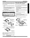
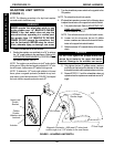
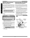
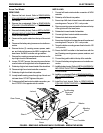
CONVENTIONAL MOTOR WITH GEARBOX
GEARLESS/BRUSHLESS MOTOR
REPLACING PNEUMATIC TIRES/
TUBES - DRIVE WHEELS/CASTERS
WARNING
DO NOT use your wheelchair unless it has the
proper tire pressure (p.s.i.). DO NOT overinflate the
tires. Failure to follow these suggestions may cause
the tire to explode and cause bodily harm.
If tires are pneumatic, replacement of tire or tube
MUST be performed by an authorized Invacare
dealer or qualified technician.
NOTE: If drive wheels or casters are pneumatic, under-in-
flation causes excessive wear which results in poor perfor-
mance of the tires.
REMOVING/INSTALLING DRIVE
WHEELS (FIGURE 1)
CAUTION
Perform the following procedure in a designated
work area to prevent damage to flooring (car-
peting, tile, etc.).
Removing
1. Remove the battery box(es). Refer to
INSTALLING/
REMOVING GROUP 24 BATTERY BOXES or IN-
STALLING/REMOVING GROUP 22 BATTERY
BOXES in PROCEDURE 9 of this manual.
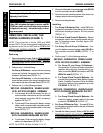
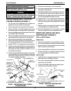
Four (4) Beveled Hex Nuts
Drive Wheel
Assembly
Wheel Hub
Assembly
*NOTE: It is not required to remove the locknut and
washer to remove the drive wheel.
PROCEDURE 12WHEELS/ MOTORS