


22
PROCEDURE 6 SEAT FRAME
S
E
A
T
F
R
A
M
E
This Procedure includes the following:
Preparation for Removing/Installing Seat Frame
(Standard Frame, Adjustable Frame,
and Captains Van Seat) ............................Page 21
Replacing Exact Same Size Standard
Seat Frame ..............................................Page 22
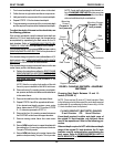
Removing/Installing Standard Seat Frame
Sub-Assembly .........................................Page 22
Changing Seat Depth ...............................Page 23
Changing Seat Width (Standard and Adjustable
Seat Frame) .............................................Page 25
Installing/Removing Adjustable Seat Frame
Sub-Assembly and/or Component
Replacement ...........................................Page 26
Installing/Removing Captains Van Seat
Assembly ................................................Page 28
Replacing Captains Van Seat and/or Captains
Van Seat Frame .......................................Page 28
Converting From Standard Seat Frame to
Adjustable Seat Frame or Vice Versa .......Page 29
Converting From Adjustable Seat Frame to
Captains Van Seat or Vice Versa...............Page 29
Converting From Standard Seat Frame to
Captains Van Seat or Vice Versa...............Page 30
Removing/Installing Seat Pan ..................Page 30
Mounting Plate - Seat Angle Adjustment and
Installation Orientation .............................Page 31
PREPARATIONS FOR REMOVING/
INSTALLING SEAT FRAME
(STANDARD FRAME, ADJUSTABLE
FRAME, AND CAPTAINS VAN SEAT)
(FIGURE 1)
NOTE: When installing/replacing components of the wheel-
chair, refer to the individual procedure for correct use of
LOCTITE 242 and torque specifications or PROCEDURE
3 of this manual.
NOTE: To reinstall these components, reverse the follow-
ing steps.
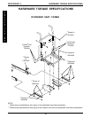
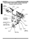
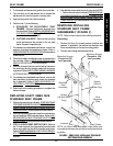
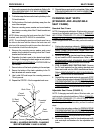
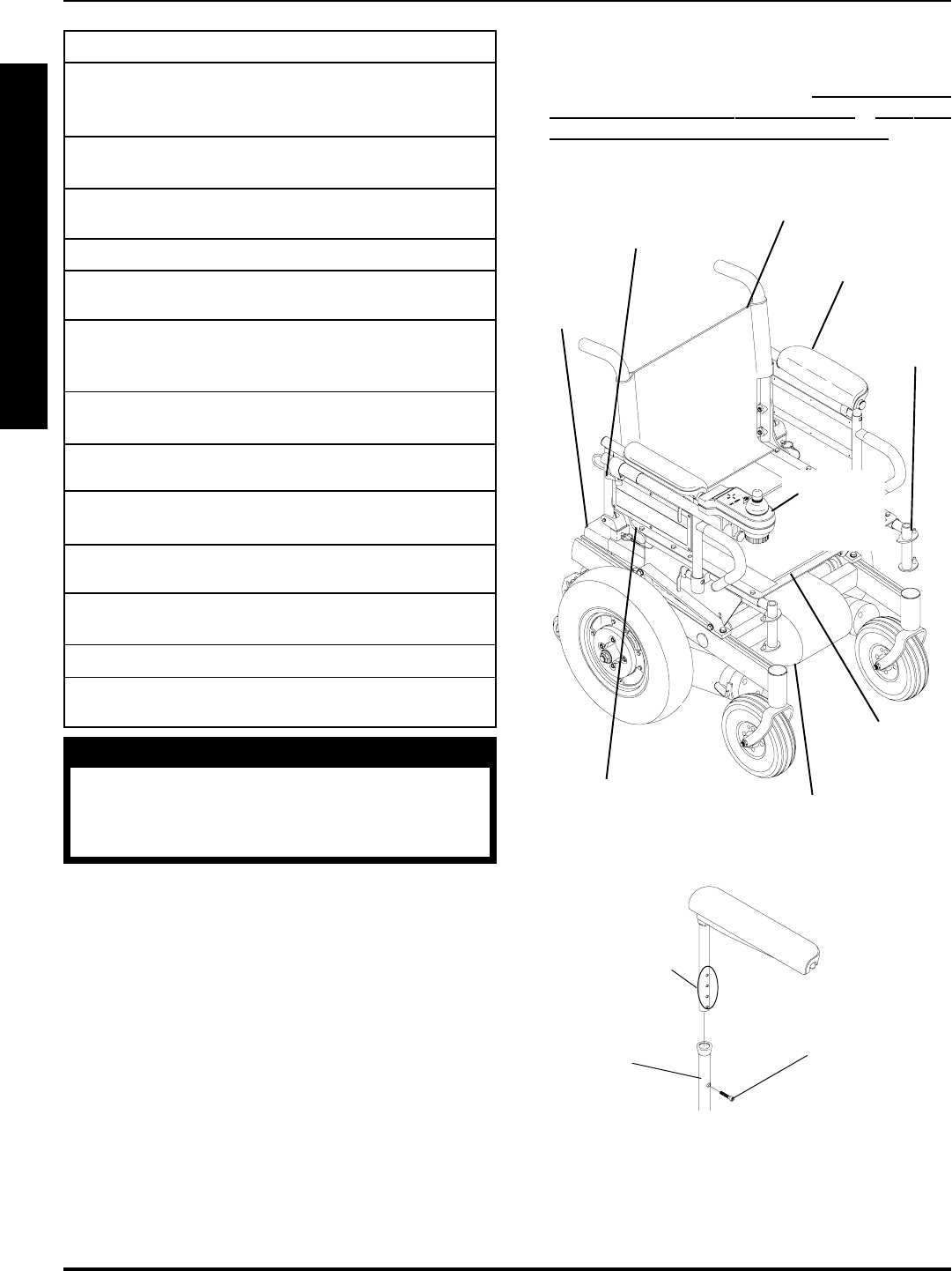
FIGURE 1 - PREPARATIONS FOR REMOVING/
INSTALLING SEAT FRAME (STANDARD FRAME,
ADJUSTABLE FRAME, AND CAPTAINS VAN SEAT)
Footrest
Location
(STEP 1)
Battery
Box(es)
(STEP 2)
Adjustment Lock
Lever for Joystick
(STEP 4)
Joystick
(STEPS
3,5)
Flip Back
Armrests
(STEP 6A)
Seat Pan
(STEP 7)
Controller, Left/Right Motor
Connectors (STEPS 8,9)
Back Upholstery
(STEP 10)
Seat Positioning
Strap (STEP 7)
NOTE: Illustration depicts tubular seat frame only. Prepa-
ration steps for the captains van seat apply in the same
manner.
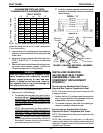
Socket
Screw
Captains
Van Seat
Base
Height
Adjustment
Holes
STEP 6B
1. Remove footrest assemblies. Refer to PROCEDURE
4 in of the owners manual, 1081227.
2. Remove battery box(es). Refer to
INSTALLING/RE-
MOVING GROUP 24 BATTERY BOXES or INSTALL-
ING/REMOVING GROUP 22 BATTERY BOX in PRO-
CEDURE 9 of this manual.
WARNING
After ANY adjustments, repair or service
and BEFORE use, make sure that all at-
taching hardware is tightened securely -
otherwise injury or damage may result.
NOTE: The procedures in this section of the manual refer
to NON-RECLINER seat frames only, EXCEPT Seat
Angle Adjustment. For recliner seat frames, refer to PRO-
CEDURE 14 of this manual.