


71
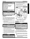
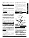
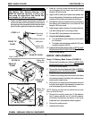
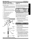
FIGURE 4 - INSTALLING GROUP 24 COMPONENTS
Mounting
Screws
Wiring Harness
w/Bracket
Battery Box
Sub-Frame
Locknuts
REAR OF CHAIR
FRONT OF
CHAIR
Spacer
Battery Box
Retainer
Bar
Battery Box
Sub-frame
REAR OF
CHAIR
Mounting Screws
Base Frame
Shock
Closed End
Retainer
Clip
STEPS 1-2
STEPS 3-6
FRONT OF
CHAIR
WARNING
The Battery Box Retainer/Retainer Clip
MUST be fastened securely in place be-
fore using the wheelchair. Use Loctite 242
and torque to 160-inch pounds.
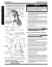
3. Position the NEW retainer clip between the NEW bat-
tery box sub-frame and shock making sure the retainer
clip mounting hole is towards the bottom and the closed
end of the clip is against the battery box retainer bar.
4. Install the mounting screw that secures the retainer
clip to the battery box sub-frame. Use Loctite 242 and
torque to 160-inch pounds.
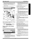
5. Align the NEW battery box retainer and spacers with
the mounting holes in the base frame making sure the
closed end of the battery box retainer is pointing up.
6. Reinstall the mounting screws that secure the battery
box retainer to the base frame. Use Loctite 242 and
torque to 160-inch pounds.
7. Install charger cable to existing mounting bracket se-
cure with existing two (2) mounting screws.
8. Tie-wrap NEW wiring harness to the seat frame.
9. Connect the following cables:
a. The right and left motor connectors to the control-
ler connectors.
b. The battery harness/charger cable (BLUE) to the
controller connector (BLUE).
10. Install the NEW battery boxes. Refer to
INSTALLING/
REMOVING GROUP 22 BATTERY BOX in PROCE-
DURE 9 of this manual.
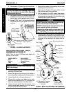
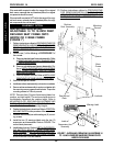
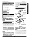
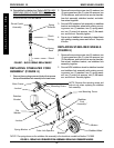
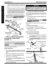
SHOCK REPLACEMENT
Group 24 Battery Base Frames (FIGURE 5)
1. Remove the front battery box. Refer to
INSTALLING/
REMOVING GROUP 24 BATTERY BOXES in PRO-
CEDURE 9 of this manual.
2. Remove the drive wheel assembly. Refer to
REMOV-
ING/INSTALLING THE DRIVE WHEEL in PROCE-
DURE 12 of this manual.
3. Loosen the mounting screw that secures the battery
box retainer between the battery box sub frame as-
sembly and the base frame.
4. Remove the mounting screw that secures the top of
the shock and retainer clip between the battery box
sub frame assembly and the base frame.
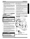
NOTE: Remove and hold onto the retainer clip for instal-
lation of the NEW shock.
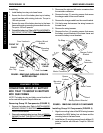
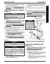
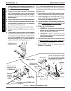
5. Remove the mounting screw, two (2) flat washers,
two (2) spring washers, two (2) inner link spacers,
and locknut that secures the bottom of the shock,
suspension arm, and stabilizer bracket together.
6. Remove the existing shock.
7. Install the NEW shock.
M
W
D
W
H
E
E
L
C
H
A
I
R
S
MWD WHEELCHAIRS PROCEDURE 15