74
PROCEDURE 15 MWD WHEELCHAIRS
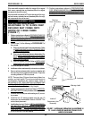
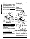
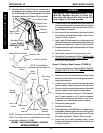
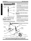
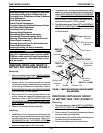
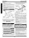
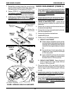
FIGURE 8 - REPLACING STABILIZER FORK ASSEMBLY/REPLACING STABILIZER WHEELS
Base Frame
Stabilizer
Fork
Assembly*
Mounting Screw
Flat
Washer
Washer
Spring Washer
Outer Link Spacers
Locknut
NOTE: Remove this mounting screw and
locknut only when replacing the stabilizer
fork assembly.
Stabilizer
Bracket
Locknut
Mounting Screw
Stabilizer Wheel
Washer
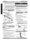
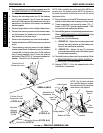
FIGURE 7 - SHOCK SPRING REPLACEMENT
Shock Eyelet
Assembly
Spring
Retainer
Shock
Spring
Spring
Base
Shock
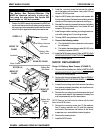
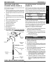
14. Reinstall the front battery box. Refer to INSTALLING/
REMOVING GROUP 24 BATTERY BOXES or IN-
STALLING/REMOVING GROUP 22 BATTERY BOX
in PROCEDURE 9 of this manual.
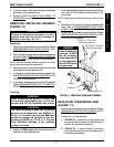
2. Remove the mounting screw, two (2) washers, two
(2) spring washers, two (2) outer link spacers, two
(2) flat washers, and locknut that secure the stabi-
lizer fork assembly, stabilizer bracket, and stabi-
lizer wheel together.
3. Secure NEW stabilizer fork assembly to stabilizer
bracket and stabilizer wheel with existing mount-
ing screw, two (2) washers, two (2) spring wash-
ers, two (2) outer link spacers, two (2) flat wash-
ers, and locknut. Securely tighten.
4. Secure top of stabilizer fork assembly to base frame
with existing mounting screw and locknut. Torque to
40 in/lbs.
REPLACING STABILIZER WHEELS
(FIGURE 8)
1. Remove the mounting screw, two (2) washers, two
(2) spring washers, two (2) outer link spacers, two
(2) flat washers, and locknut that secure the stabi-
lizer wheel, stabilizer bracket, and stabilizer fork
assembly together.
2. Secure NEW stabilizer wheel to stabilizer bracket
and stabilizer fork assembly with existing mount-
ing screw, two (2) washers, two (2) spring wash-
ers, two (2) outer link spacers, two (2) flat wash-
ers, and locknut. Securely tighten.
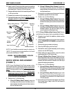
REPLACING STABILIZER FORK
ASSEMBLY (FIGURE 8)
1. Remove the mounting screw and locknut that secures
the top of the stabilizer fork assembly to the base frame.
M
W
D
W
H
E
E
L
C
H
A
I
R
S
*NOTE: The spring shown on the stabilizer fork assembly is for wheelchair models built before 7/1/1999


