


23
3. Cut tie wraps and disconnect joystick from controller.
4. Turn the lever on the adjustment lock to release the
adjustment lock from the joystick mounting tube.
5. Remove the joystick from the wheelchair.
6. Perform one (1) of the following:
A. STANDARD OR ADJUSTABLE SEAT
FRAMES - Remove the flip-back armrests from
the wheelchair. Refer to
INSTALLING/REMOVING
FLIP BACK ARMRESTS in PROCEDURE 4 of
the owners manual, 1081227.
B. CAPTAINS VAN SEAT - Remove the mounting
screw that secures the armrest to the van seat
frame. Repeat for opposite side.
7. For standard and adjustable seat frames, remove the
seat pan (including seat positioning straps). Refer to
REMOVING/INSTALLING SEAT PAN in this procedure
of the manual.
8. Disconnect battery and left/right motor connectors from
the controller. Refer to
REPLACING WIRING HAR-
NESS in PROCEDURE 10 of this manual.
9. Remove tie-wraps that secures the wiring harness to
the seat frame and the charger cable from its mount-
ing bracket. Refer to
REPLACING WIRING HARNESS
in PROCEDURE 10 of this manual.
10. For standard and adjustable seat frames, remove the
back upholstery (including back canes and spreader
bar, if applicable). Refer to
REPLACING BACK UP-
HOLSTERY in PROCEDURE 5 of the manual.
11. Refer back to the starting procedure to complete the
desired change.
REPLACING EXACT SAME SIZE
STANDARD SEAT FRAME
1. Perform the instructions outlined in PREPARATIONS
FOR REMOVING/INSTALLING SEAT FRAME (STAN-
DARD FRAME, ADJUSTABLE FRAME, AND CAP-
TAINS VAN SEAT) in this procedure of the manual.
2. Remove the existing standard seat frame subassem-
bly and install the NEW standard frame. Refer to
RE-
MOVING/INSTALLING STANDARD SEAT FRAME
SUBASSEMBLY in this procedure of the manual.
3. FOR 12-15-INCH SEAT DEPTHS ONLY: Remove
the CJ back brackets from the existing standard seat
frame and install onto the NEW standard seat frame.
Refer to
REMOVING/INSTALLING CJ BACK BRACK-
ETS FROM SEAT FRAME in this procedure of the
manual.
4. Reinstall the components previously removed in STEP
1. Perform the instructions outlined in
PREPARATIONS
FOR REMOVING/INSTALLING SEAT FRAME (STAN-
DARD FRAME, ADJUSTABLE FRAME, AND CAP-
TAINS VAN SEAT) in this procedure of the manual.
REMOVING/INSTALLING
STANDARD SEAT FRAME
SUBASSEMBLY (FIGURE 2)
NOTE: Perform steps required from starting procedure.
Removing
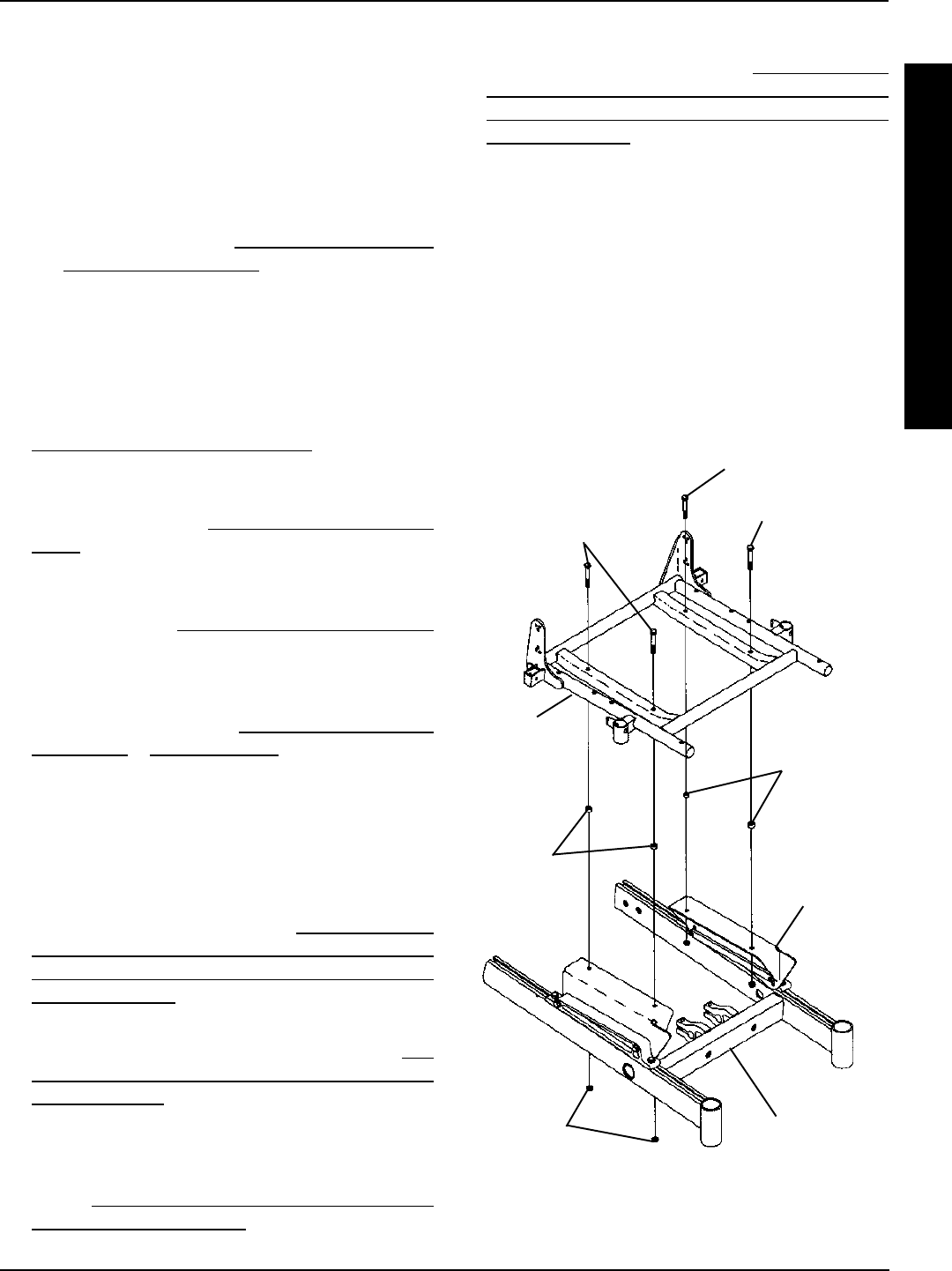
1. Remove the four (4) mounting screws, locknuts and
spacers, if applicable, that secure the standard seat
frame subassembly to the seat mounting plates.
2. Remove the existing standard seat frame.
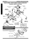
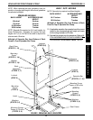
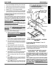
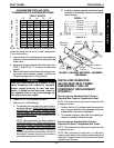
FIGURE 2 - REMOVING/INSTALLING STANDARD
SEAT FRAME SUB-ASSEMBLY
Mounting Screws
(Torque to 156-
inch pounds)
Standard
Seat
Assembly
Locknuts
Base Frame
Spacer
(16-inch
Wide Only)
Seat
Mounting
Plate
Spacer
(16-inch Wide
Only)
Mounting Screws
(Torque to 156-
inch pounds)
NOTE: For 16-inch wide seat frames, there will be spac-
ers positioned between the seat frame and the seat mount-
ing plates.
S
E
A
T
F
R
A
M
E
PROCEDURE 6SEAT FRAME