


89
12. Install the shock onto the new suspension arm. Refer
to
REMOVING/INSTALLING THE SHOCK ASSEM-
BLY in this procedure of the manual.
13. Install the motor onto the new suspension arm. Refer
to
REMOVING/INSTALLING THE MOTOR in PRO-
CEDURE 12 of this manual.
14. Install anti-tip assembly onto the rear of the new sus-
pension arm. Refer to
REMOVING/INSTALLING THE
ANTI-TIP ASSEMBLY in this procedure of the manual.
15. Perform one (1) of the following:
A. Remove the seating system. Refer to the seating
systems owners manual for removal/installation
instructions.
B. Remove the seat pan. Refer to
REMOVING/IN-
STALLING THE SEAT PAN in PROCEDURE 6 of
this manual.
RWD WHEELCHAIRS PROCEDURE 16
R
W
D
W
H
E
E
L
C
H
A
I
R
S
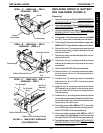
8. Torque suspension arm hex screws (1/2 x 7-inches) to
85 FOOT pounds (approximately 1,020-inch pounds)
and replace plug buttons.
9. Reinstall the gearbox onto the existing suspension arm.
Refer to
REMOVING/INSTALLING GEARBOX in this
procedure of the manual.
10. Tighten the hex screws that secure wiring harness to
sub-frame assembly securely.
11. Reinstall the drive wheel onto the wheelchair. Refer to
REMOVING/INSTALLING DRIVE WHEELS in PRO-
CEDURE 12 of this manual.
12. Repeat STEPS 1-12 for the opposite side of the wheel-
chair, if necessary.
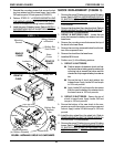
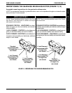
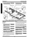
REPLACING SUSPENSION ARM
FOR WHEELCHAIRS WITH
GEARLESS/BRUSHLESS MOTORS
(FIGURE 16)
1. Perform one (1) of the following:
A. Remove the seating system. Refer to the seating
systems owners manual for removal/installation
instructions.
B. Remove the seat pan. Refer to
REMOVING/IN-
STALLING THE SEAT PAN in PROCEDURE 6 of
this manual.
2. Remove the motor. Refer to
REMOVING/INSTALLING
THE MOTOR in PROCEDURE 12 of this manual.
3. Cut the tie-wrap(s) that secure the wiring harness/
charger cable to the suspension arm.
4. Remove the anti-tip assembly from the rear of the sus-
pension arm. Refer to
REMOVING/INSTALLING THE
ANTI-TIP ASSEMBLY in this procedure of the manual.
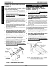
5. Remove the shock from the suspension arm. Refer to
REMOVING/INSTALLING THE SHOCK ASSEMBLY
in this procedure of the manual.
6. Remove the plug buttons from the side of the base
frame.
7. Remove the mounting screw and beveled washers
that secure the front of the suspension arm to the base
frame.
8. Remove the existing suspension arm from the base
frame.
9. Install the new suspension arm onto the base frame.
10. Install mounting screw and beveled washers that se-
cure the front of the suspension arm to the base frame.
11. Install the plug buttons into the side of the base frame
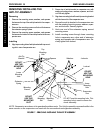
Suspension Arm Hex Screw
(1/2 x 7-inches)
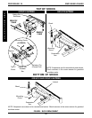
FIGURE 16 - REPLACING SUSPENSION ARM FOR
WHEELCHAIRS WITH GEARLESS/BRUSHLESS MOTOR
Suspension Arm
Plug
Button
Beveled
Washers
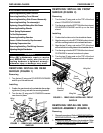
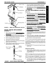
Anti-Tipper Wheel
Locknut
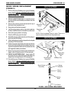
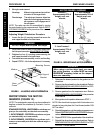
ANTI-TIPPER WHEEL
REPLACEMENT (FIGURE 9)
1. Remove the locknuts, hex screws and spacers that
secure the anti-tipper wheels to the shock mount plates.
2. Replace anti-tipper wheel(s) and torque existing hard-
ware to 30-35-inch pounds. DO NOT overtighten.
Spacer
FIGURE 9 - ANTI-TIPPER WHEEL REPLACEMENT
Hex Screw
Shock Mount Plates