


SECTION 12—ANTI-TIPPERS
Part No. 1125078 71 At’m and At’m QT
SECTION 12—ANTI-TIPPERS
ƽ WARNING
After any adjustments, repair or service and before use, make sure that all attaching
hardware is tightened securely - otherwise injury or damage may result.
Before performing any maintenance, adjustment or service verify that on/off switch
on the joystick is in the off position.
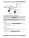
Removing/Installing the Anti-Tippers
ƽ WARNING
Anti-tippers MUST be fully engaged before using the wheelchair.
Ensure both anti-tippers have the same ground clearance.
A 1½ to 2-inch clearance between the bottom of the anti-tipper wheels and the
ground/floor MUST be maintained at all times.
Anti-tippers MUST be used at all times. When outdoors on wet, soft ground or
gravel surfaces, anti tippers may not provide the same level of protection against tip
over. Extra caution must be observed when traversing such surfaces.
At’m
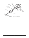
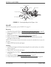
NOTE: For this procedure, refer to FIGURE 12.1 on page 72.
Removing
1. Disconnect the joystick. Refer to Disconnecting/Connecting the Joystick on page 40.
2. Remove the battery pack. Refer to Removing/Installing the Battery Pack on the At’m
on page 45.
3. Remove the seat. Refer to Removing/Installing the Seat on page 31.
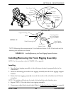
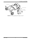
4. Remove the two mounting bolts, four washers, two locknuts, and four coved washers
that secure the anti-tipper to the base frame (FIGURE 12.1).
5. Repeat STEP 4 for the other anti-tipper.
Installing
1. Install the anti-tippers to the base frame using the two mounting bolts, four washers,
two locknuts, and four coved washers that secure the anti-tipper to the base frame
(FIGURE 12.1).
2. Repeat STEP 1 for the other anti-tipper.
3. Install the battery pack. Refer to Removing/Installing the Battery Pack on the At’m on
page 45.
4. Connect the joystick. Refer to Disconnecting/Connecting the Joystick
on page 40.