


SECTION 8—BATTERIES
At’m and At’m QT 50 Part No. 1125078
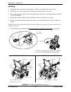
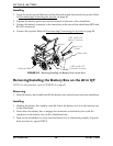
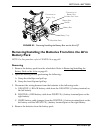
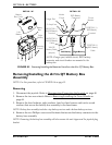
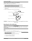
FIGURE 8.5 Removing/Installing the Batteries From/Into the At’m QT Battery Box
Removing/Installing the At’tm QT Battery Box
Assembly
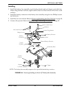
NOTE: For this procedure, refer to FIGURE 8.6 on page 51.
Removing
1. Disconnect the joystick. Refer to Disconnecting/Connecting the Joystick on page 40.
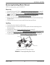
2. Remove the two rear wheels. Refer to Removing/Installing the Drive Wheels on
page 69.
3. Remove the four locknuts, eight washers, four hex head screws and twelve coved
washers that secure the battery box assembly to the base frame.
NOTE: Battery box assembly includes a top battery receiver and a bottom battery receiver.
4. Remove the two Phillips
®
screws and locknuts that secure the battery connector to the
battery box assembly.
NOTE: Removing the battery box assembly will also remove the anti-tipper and the joystick plug
bracket.
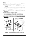
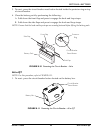
DETAIL “A”
Mounting
Screws
Battery
Box
Left
Battery
Battery
Box Cover
DETAIL “B”
Right Battery
Left Battery
POSITIVE (+)
RED Battery
Cable
10 Amp Fuse
Circuit
Breaker
POSITIVE (+)
RED Battery
Terminal
NEGATIVE (-)
BLACK Battery
Terminal
NEGATIVE (-)
BLACK Battery
Cable
WHITE
Battery Cable
(Jumper)
RED Battery
Connector
Right
Battery
Charger Port
Inhibit
Circuit
NOTE: Charger port, inhibit circuit, RED battery
connector and circuit breaker are mounted to the
battery box.