


SECTION 9—MOTORS
At’m and At’m QT 60 Part No. 1125078
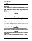
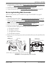
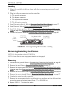
Installing
1. Mount the controller to the base frame with the two mounting screws and coved
washers.
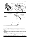
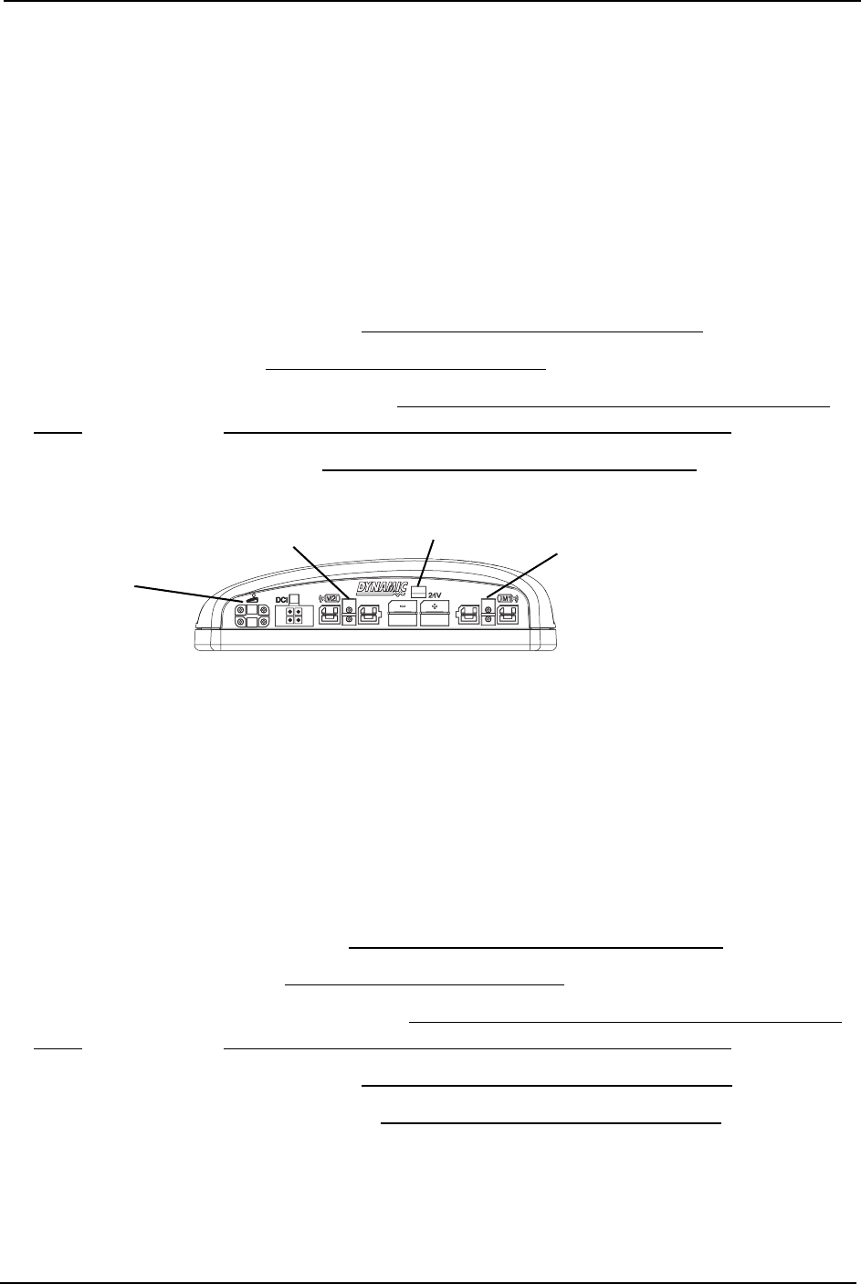
2. Plug the following connectors into the controller:
A. The joystick connector
B. The battery connector
C. The right motor connector
D. The left motor connector
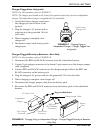
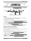
3. Install the motor shroud. Refer to Removing/Installing Motor Shroud on page 57.
4. Install the seat. Refer to Removing/Installing the Seat on page 31.
5. Install tthe battery pack/box. Refer to Removing/Installing the Battery Pack on the
At’m on page 45 or Removing/Installing the Battery Box on the At’m QT on page 46.
6. Connect the joystick. Refer to Disconnecting/Connecting the Joystick
on page 40.
FIGURE 9.5 Removing/Installing MK5 Controller - Installing
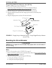
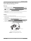
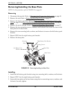
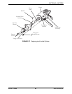
Removing/Installing the Motors
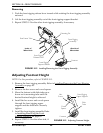
NOTE: For this procedure, refer to FIGURE 9.6.
NOTE: Ensure that the motor engagement handles are disengaged.
Removing
1. Disconnect the joystick. Refer to Disconnecting/Connecting the Joystick on page 40.
2. Remove the seat. Refer to Removing/Installing the Seat on page 31.
3. Remove the battery pack/box. Refer to Removing/Installing the Battery Pack on the
At’m on page 45 or Removing/Installing the Battery Box on the At’m QT on page 46.
4. Remove the drive wheel. Refer to Removing/Installing the Drive Wheels
on page 69.
5. Remove the motor shroud. Refer to Removing/Installing Motor Shroud
on page 57.
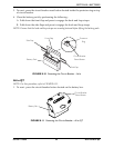
6. Unplug the motor from the controller.
7. Remove the two mounting bolts, coved bracket, two washers, and two locknuts that
secure the motor to the base frame (Detail “B” of FIGURE 9.6).
8. Repeat STEPS 1 - 7 for the other motor.
Plug
Joystick
HERE
Plug LEFT
Motor HERE
Plug RIGHT
Motor HERE
Plug Battery HERE