


SECTION 3—SAFETY INSPECTION/TROUBLESHOOTING
Part No. 1125078 29 At’m and At’m QT
Electro-Mechanical Parking Brake Test
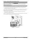
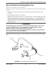
NOTE: For this procedure, refer to FIGURE 3.2.
NOTE: This procedure should only be performed on wheelchairs with conventional motor/gearbox
assembly.
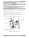
1. On the four-pin motor connector, locate the side by side connectors in the black
housings.
2. Set the digital multimeter to read ohms.
3. Measure the resistance between the two brake contacts. A normal reading is between
45-100 ohms depending on the motor. A reading of 0 ohms or a very high reading; i.e.,
MEG ohms or O.L. (out of limit) indicates a shorted brake or an open connection
respectively. If either condition exists, send the motor to Invacare Technical Service for
inspection/repair.
ƽ WARNING
A shorted electro-mechanical brake will damage the brake output section in the
controller. DO NOT connect a shorted electro-mechanical brake to a good
controller module. A shorted brake MUST be replaced.
Proper controller operation regarding brake function should be performed when-
ever a shorted brake is found and replaced.
NOTE: A bad motor can damage the controller module but a bad controller will NOT damage a
motor.
.
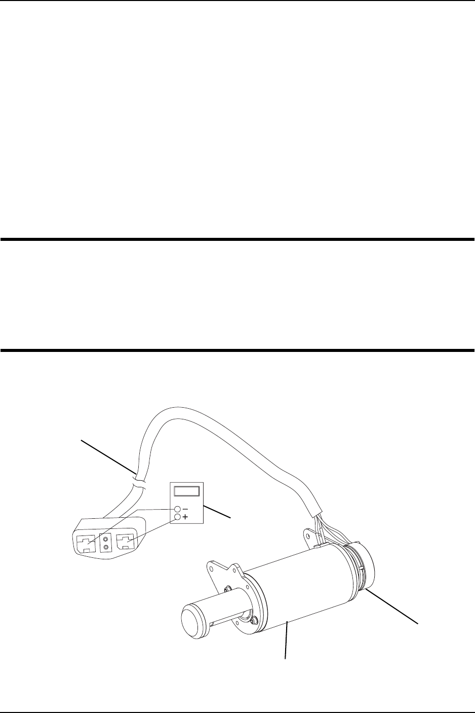
FIGURE 3.2 Electro-Mechanical Parking Brake Test
4 Pin Motor
Connector
Motor
Cap
Digital
Multimeter