


1594A/1595A Super-Thermometer
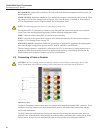
Scanning Multiple Temperature Probes
62
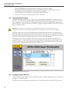
7. If the desired measurement channel is set to Off, use the ON/OFF (F3) function key to toggle the
channel to On. Pressing the Channel Select key located above the channel connection will also set the
channel to On.
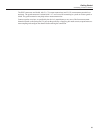
8. Press the EXIT key twice (or press and hold the EXIT key) to go to the Measurement screen.
9. In the Measurement screen, select the START MEASURE (F1) function key to start measurement
sampling.
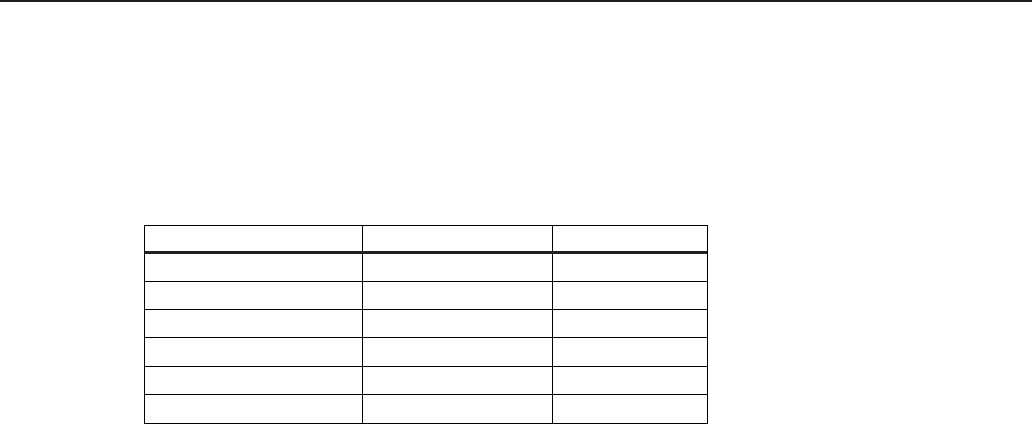
Table 17 Recommended Reference Resistors and Sensing Current
Probe Type Reference Resistance Sensing Current
25 W SPRT 25 W
1.0 mA
100 W PRT or RTD 100 W
1.0 mA
2.5 W SPRT 10 W
5.0 mA
0.25 W SPRT 1 W
14.14 mA
1000 W PRT or RTD 10 kW
0.05 mA
Thermistors, 2 kW to 10 kW 10 kW
0.01 mA
7.3 Scanning Multiple Temperature Probes
Use the following instructions to congure the Super-Thermometer for scanning multiple temperature probes.
1. Follow the steps in the previous section “Measuring a Temperature Probe” to connect and configure two
or more temperature probes.
2. Press the MENU key to open the Main Menu screen.
3. Select the MEASURE MENU (F3) function key to open the Measure menu.
4. Select the SCAN SETTINGS (F1) function key.
5. Set SCAN ENABLE to On. If needed, configure the other scan settings.
6. Press the SETUP key.
7. In the Channel Setup screen, ensure that each channel to which a probe is connected is enabled (set to
ON). Disable all other channels by setting them to Off. An alternative method is to press the channel
select key above each channel to enable or disable the channel in the scan sequence.
8. Press and hold the EXIT key to return to the Measurement screen.
9. Begin scanning by selecting the START MEASUREMENT (F1) function key.
7.4 Measuring Resistance Ratio
The ratio measurement is the fundamental measurement from which the resistance and temperature measure-
ments are derived. It is simply the ratio (Rx/Rs) between an unknown resistance (Rx) and a reference resistor
(Rs).
To congure the Super-Thermometer for ratio measurement, follow the steps listed in section 5.2 except select
RATIO in step 6.d.
7.5 Conguring an External Reference Resistor
The Super-Thermometer is equipped with a set of internal resistors. If needed, up to four external resistors can
be connected using Rs1 and Rs2 inputs on the back panel and Ch2 and Ch4 inputs on the front panel. Use the
following instructions for connecting and measuring with an external resistor:
1. Suspend measurement by going to the Measurement screen and pressing the STOP MEASUREMENT
(F1) function key.
2. Connect a reference resistor using one of the Rs inputs. Ensure the current and potential connections are
correct.
3. Go to the Add Resistor screen by using the following steps:
a. Press the SETUP key to open the Channel Setup screen.
b. Select the CHANNEL SETTINGS (F2) function key.