


17
Front and Rear Panel Features
Front Panel Features
4 Front and Rear Panel Features
4.1 Introduction
The Super-Thermometer has been designed with several features that help make setup and operation as simple
as possible while still providing many measurement capabilities. This section describes the front and rear
panel features as well as the menu system. Please read this section before operating the instrument.
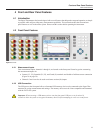
4.2 Front Panel Features
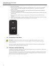
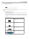
Figure 2 Front view
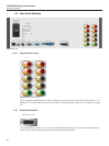
4.2.1 Measurement Inputs
Four measurement inputs, channels 1 through 4, are located on the front panel. Some key points concerning
the measurement inputs are:
●
Current (C1, C2), Potential (P1, P2), and Guard (G) terminals are labeled to facilitate correct connection
(Figure 16 on page 58).
●
Channels 2 and 4 can also be used as reference resistor (Rs) inputs.
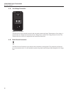
4.2.2 USB Connection
The USB port on the front panel allows a formatted USB memory device to be connected to the Super-Ther-
mometer for saving measurements and settings. The memory device must be Linux compatible and formatted
with the FAT32 le system.
Important: When inserting a USB memory device into the front panel USB port, wait for about 10
seconds to allow the system to recognize the memory device before attempting to write to or read from it.