


61
Making Measurements
Measuring a Temperature Probe
7 Making Measurements
7.1 Introduction
The Super-Thermometer has been designed to allow quick and easy measurement setup while providing ex-
ible measurement options. The purpose of this section is to guide the user through the conguration of the
Super-Thermometer for typical measurements.
7.2 Measuring a Temperature Probe
The following instructions apply to the setup of both PRTs and thermistors for temperature measurement.
1. Press and hold the EXIT key to go to the Measurement screen.
2. If necessary, suspend measurement by pressing the STOP MEASUREMENT (F1) function key.
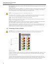
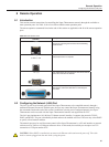
3. Using the instructions in the Getting Started section, connect a temperature probe to one of the
measurement input channels.
4. Press the SETUP key to open the Channel Setup screen. Use the Up/Down arrow keys to highlight
the channel to which the probe is connected. Scanner channels, if available, are identified with a S1
(scanner 1) or S2 (scanner 2) prefix added to the channel number.
5. Once the channel is highlighted, use the following steps to assign a probe definition to the selected
channel.
a. Select the ASSIGN PROBE (F1) function key to open the Probe Library.
b. Scroll through the list of probe denitions using the Up/Down arrow keys to locate the probe’s
denition. If the probe denition has not been previously entered, select ADD PROBE (F1)
to begin the process of creating a probe denition (see Section 5.7.2, PROBE MENU (F2), on
page 34 for more information).
c. When the probe denition is selected, press the ENTER key to assign the selected probe
denition to the channel and return to the Channel Setup menu.
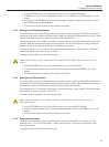
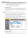
6. Select the CHANNEL SETTINGS (F2) function key to configure the measurement channel using the
following steps:
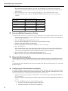
a. Select the desired reference resistor (Rs) to be used for the measurement by pressing the Left/
Right arrow keys and pressing ENTER to conrm the selection. Use “Table 17 Recommended
Reference Resistors and Sensing Current” on page 62 as a guide for the selection.
b. Enter the correct sensing current using Table 17 on page 62 or the probe manufacturer’s
instructions as a guide.
c. Determine whether standby current (see Channel Setup section) is to be On or Off.
d. Select the desired measurement calculation. The options are RESISTANCE (to output the
probe’s resistance only), RATIO (to output the ratio of the probe’s resistance versus the
reference resistor), and TEMPERATURE (only if calibration coefcients were entered in the
probe denition).
e. Press the EXIT key to move back to the Channel Setup screen.