


41
Menus and Screens
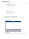
Main Menu
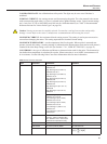
PRESET PRECISION (F2) - sets the timing settings for minimal measurement noise and settling error with
most thermometer probes. Sample Period is set to 2 seconds, Display Interval is set to 10 seconds, and Aver-
age Enable is set to ON.
PRESET FAST (F3) - is used to congure the Super-Thermometer for the fastest possible measurements.
Sample Period and Display Interval are both set to 1 second. Measurement noise and electrical settling errors
may be greater in Fast mode. Fast mode is useful for certain applications such as probe response time testing.
PRESET LONG (F4) - sets the timings settings for better results with probes that exhibit long electrical set-
tling times. Measurement noise might be slightly higher. Sample period is set to 10 seconds, Display Interval
is set to 10 seconds and Average is set to ON.
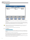
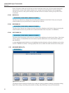
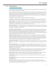
5.7.3.3 DIGITAL FILTER (F3)
MAIN MENU | MEASURE MENU |
The Digital Filter screen is used to change the digital lter settings and clear the digital lter buffer.
Digital Filter Description
The digital lter is a moving average lter that computes the arithmetic mean of display measurements stored
in a buffer. The size of the buffer is user-dened via the Average Count setting. If the buffer is full, the oldest
measurement in the buffer is discarded when a new measurement enters the buffer. If the buffer is only partly
lled, the mean is still computed using the limited number of stored measurements.
If the digital lter is enabled, the most recent measurement coming from Averaging (see Measurement Se-
quence Diagram in the previous section) is averaged with the previous display measurements stored in the
digital lter buffer. For example, if Display Interval is set to 10 seconds, and the digital lter average count is
20, a new display measurement is averaged with the previous 19 display measurements for a window size of
200 seconds (n = 20).
The buffer is cleared when measurement is started or if a measurement is out-of-range. This may occur, for
example, if a probe is disconnected from a channel. It may also be cleared by the user at any time using the
CLEAR FILTER (F1) function. This clears the lter for all channels at once.
The Digital Filter conguration settings and function key are as follows:
FILTER ENABLE - enables or disables the digital lter. The default option is ON.
AVERAGE COUNT - sets the number of Display Interval measurements that are averaged by the digital
lter. The setting has a range of 2 through 100. The default value is 30. This setting is only meaningful when
Filter Enable is ON.
5.7.3.3.1 CLEAR FILTER (F1) - clears the lter buffer.
Tip: It is useful to use Clear Filter to clear the digital lter buffer when an abrupt change to the data
has occurred. This allows the ltered measurements to settle more quickly.
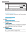
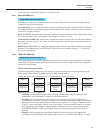
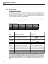
5.7.3.4 RECORDING MENU (F4)
MAIN MENU | MEASURE MENU |
In the Recording Menu, the user can control how measurements are recorded to a memory device (external or
internal). This menu is also used for manipulating data les including exporting of data and erasing data.
Measurements may be stored in either of two possible memory devices; Internal Memory or a external USB
Memory Device. Internal memory can store up to approximately 80,000 individual measurements. A USB
ash memory device can typically store an even greater quantity of data, depending on the memory size. Both
types of memory devices are non-volatile, meaning the data is preserved even when the power is switched off.
However, some data may be lost if the power is switched off as data is being written.