21
Front and Rear Panel Features
Rear Panel Features
4.3.2 Future Peripheral Connection
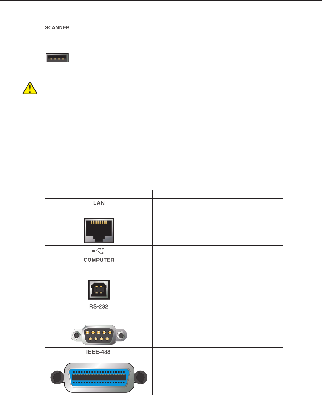
A USB peripheral port is intended for future peripheral control.
Note: This port is NOT used for external memory connection. For external memory via USB see Section
4.2.2, USB Connection, on page 17 and Figure 2 on page 17.
4.3.3 Remote Operation Connections
The Super-Thermometer comes equipped with several remote operation connections. See Table 11 for the
remote operation connection descriptions.
Using the LAN connection and a web browser, the user is able to operate the Super-Thermometer remotely via
the provided web interface. The Super-Thermometer serves a page that allows the user to view the display and
control the Super-Thermometer through the web browser. For more information, refer to the Remote Opera-
tion section.
Table 11 Remote Operation Connections
Connection
Description
Ethernet connector that allows connection to a
network for controlling the instrument and transmitting
measurements
USB port that allows the instrument to be controlled as a
USB peripheral from a computer
9-pin subminiature D type serial port that can be used to
control the instrument via RS-232
IEEE-488 Input/Output that is compatible with IEEE-
488 interface and the IEC 625 Bus for controlling the
instrument


