


103
Calibration
CURRENT TEST (F2)
9 Calibration
9.1 Introduction
This section explains the step-by-step instructions for calibrating and verifying functionality of the Super-
Thermometer to ensure it will operate correctly and meet published specications. If the instrument cannot be
brought into specication using these instructions, contact the nearest Fluke Authorized Service Center.
A complete Super-Thermometer calibration is comprised of four parts; Self Test, Ratio Self-Calibration, Inter-
nal Resistor Calibration, and Current Test. The user may perform all four parts or only a single part if desired.
Built-in functions automate all of the test and calibration steps except Current Test. The functions are found in
the Calibration menu. Go to the Calibration menu by pressing the MENU key then the SYSTEM MENU (F5)
function key followed by the CALIBRATION (F5) function key.
The unit should be allowed to warm up for at least 30 minutes before performing any calibration.
Self Test can be performed at any time during or after the warm up period.
IMPORTANT: Make sure the OVEN indicator on the Measurement Screen shows READY before performing
any calibration.
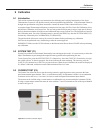
9.2 SYSTEM TEST (F1)
System Test performs several internal functionality tests and reports the results. It is not necessary to allow the
Super-Thermometer to pass through the required warm-up period before performing this test.
To run System Test, press the SYSTEM TEST (F1) function key. Press the START (F1) function key to begin
the system self-test. As the test proceeds, the screen indicates the time remaining. The user may press the
CANCEL (F5) function key or EXIT key to cancel the test. When the test is nished, the results are displayed.
If a failure is indicated, contact the nearest Fluke Authorized Service Center.
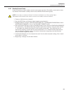
9.3 CURRENT TEST (F2)
The Current Test allows the user to test the sensing current by applying non-reversing current to the front
panel measurement input channels. This is a verication test only, no adjustment is made. It is recommended
to measure at least 0.01 mA, 1.0 mA and 1.414 mA on each front panel measurement input channel.
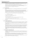
The current can be veried using a current meter or a calibrated 4-wire resistor and digital voltmeter (DVM).
If using a current meter, connect the meter in series with the C1 and C2 terminals on one of the input channels
as shown in Figure 18.
Figure 18 Current meter connection diagram