


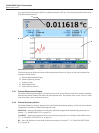

1594A/1595A Super-Thermometer
Main Menu
30
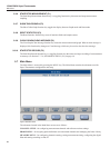
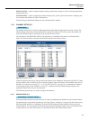
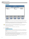
5.7.1.2 CHANNEL SETTINGS (F2)
MAIN MENU | CHANNEL SETUP |
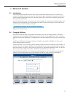
With the desired channel selected in the Channel Setup screen, pressing the Channel Settings function key
opens a screen that allows the user to congure the channel settings. The channel that is being congured is
identied at the top of the Channel Settings screen.
The channel conguration elds are as follows:
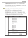
REFERENCE RESISTOR (Rs) - identies the reference resistor to be used for measurement. The options
are any of the four internal resistors (1Ω, 10Ω, 25Ω, 100Ω, 10 kΩ) and any user-congured external resistor.
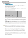
See Table 13 for the recommended reference resistor.
Table 13 Recommended Reference Resistor for Various Probe Types
Probe Type Reference Resistance Sensing Current
25 W SPRT 25 W
1.0 mA
100 W PRT or RTD 100 W
1.0 mA
2.5 W SPRT 10 W
5.0 mA
0.25 W SPRT 1 W
14.14 mA
1000 W PRT or RTD 10 kW
0.05 mA
Thermistors, 2 kW to 20 kW 10 kW
0.01 mA
Thermistors, 20 kW to 100 kW 10 kW
0.002 mA
SENSING CURRENT - the excitation current used for measurement. By default, it is set to the nominal
current value entered in the probe’s denition. However, if the user enters a different sensing current, the new
value will supersede the probe denition.
The 1 x POWER (F2) function key automatically sets Sensing Current to the Nominal Current value estab-
lished in the probe denition. 2 x POWER (F3) sets Sensing Current to 1.4142 times the nominal current. In
order to protect the device being measured, the current is limited by the Maximum Current setting in the probe
denition.
STANDBY CURRENT- allows current to pass through a probe or resistor even when it is not being actively
measured. This is useful for keeping the probe self-heated so it will need less time to settle when measured.
The magnitude of the standby current is the same as the Sensing Current as long as the Sensing Current is no
greater than 2 mA. If the Sensing Current is greater than 2 mA, the channel’s standby current will remain off
regardless of the Standby Current setting.
Important: All currents are switched off when Measurement is stopped. Also, when Scan Enable is on
(see Scan Enable in Section 5.7.3.1, SCAN SETTINGS (F1), on page 39), only those channels that are
enabled for measurement will have standby current on, depending on the Sensing Current and Standby
Current settings.
Tip: A probe’s sensing element is heated as current passes through it. This effect is called self-heating.
Self-heating causes a probe’s measured temperature to change slightly due to the heat being dissipated.
The measurement error associated with self-heating depends on probe design and the level of
measurement current. To measure the effect of self-heating, use the Zero-Power function in the Measure
Menu, see Section 5.7.3.5, ZERO-POWER MEASUREMENT (F5), on page 43 .
CALCULATION - determines the type of reading the channel measurement will display. The options are
RESISTANCE, RATIO and TEMPERATURE. The TEMPERATURE option is available only if a probe de-
nition, congured for temperature measurement, has been assigned to the channel (see Section 5.7.2, PROBE
MENU (F2), on page 34). The Resistance option is not available if the channel’s Reference Resistor (Rs)
setting is set to Variable Resistance.