


1594A/1595A Super-Thermometer
Measurement Screen
26
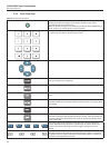
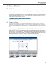
or by pressing and releasing the MENU key then pressing the EXIT key. The following describe each section
of the Measurement Screen.
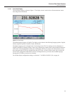
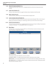
Figure 9
A
B
C
D
E
Measurement Screen
The following are the different sections of the Measurement Screen (see Figure 9) followed by detailed de-
scriptions of each section:
A. Channel Measurement Display
B. Channel Summary Section
C. Statistics Fields
D. Data/Graph Section
E. Status and Alert Section
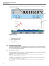
5.6.1 Channel Measurement Display
The Channel Measurement Display is located at the top of the screen and shows the most recently completed
measurement and the channel from where the measurement came. This portion of the screen is always visible,
even when other screens and menus are open.
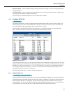
5.6.2 Channel Summary Section
The Channel Summary Section, directly below the Channel Measurement Display, on the left, shows channel
conguration information with the following four elds.
PROBE ID – shows the identication of the probe denition assigned to the channel being measured (see
Section 5.7.2, PROBE MENU (F2), on page 34)
CURRENT – shows the excitation current used in measuring the probe (see Sensing Current under Section
5.7.1.2, CHANNEL SETTINGS (F2), on page 30
RS – shows the reference resistor used for the measurement (see Section 5.7.1.2, CHANNEL SETTINGS
(F2), on page 30).