


1594A/1595A Super-Thermometer
RATIO CALIBRATION (F3)
104
If using a calibrated resistor, connect the resistor to all four terminals on one of the front panel measurement
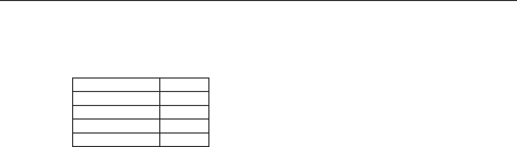
inputs and connect the voltmeter to the P1 and P2 terminals. Refer to Table 20 for recommended resistance
values. The accuracy of the DVM should be better than 0.05 % over the range of 0.02 V to 0.2 V.
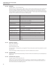
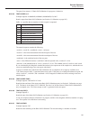
Table 20 Recommended Resistors For Testing The Current
Current Resistor
0.001 mA to 0.02 mA 10 kW
0.02 mA to 0.2 mA 1 kW
0.2 mA to 2.0 mA 100W
2.0 mA to 20.0 mA 10 W
To start the test, press the CURRENT TEST (F2) function key located in the Calibration menu. The following
elds are used to congure each step of the test.
CHANNEL - the input channel being tested
CURRENT - the sensing current value
POLARITY - species the direction of the sensing current, either forward or reverse
Select the START (F1) function key to begin the current test. Constant current is applied to the specied chan-
nel allowing current measurements to be measured by the current meter or voltage readings to be taken across
the resistor. During current test, the channel’s LED indicator is illuminated green. The channel, current, and
polarity may be changed during the test.
Current Test is stopped by pressing the STOP (F1) function key or the EXIT key. This switches off the sensing
current allowing the user to connect a different resistor or change any of the conguration elds. Press the
EXIT key to leave the test screen.
If using the calibrated resistor and voltmeter method, calculate the actual current by dividing the measured
voltage by the value of the resistor. The difference between the actual measured current and the current setting
should be within the measurement current accuracy. If the current is not within specication, contact the near-
est Fluke Authorized Service Center for more information.
9.4 RATIO CALIBRATION (F3)
The Ratio Self-Calibration function allows the user to perform a ratio linearity check or calibration using an
internal resistor network. No other test equipment is required. Due to the simplicity and short time the test
takes to run, Ratio Self-Calibration can be performed as often as needed.
Caution: Ratio Self-Calibration does not test resistance accuracy or calibrate the internal reference resistors.
Running the Ratio Self-Calibration function does not require a password. This is because it reports the results
of the linearity test only. If adjustment is needed, the Adjust Parameters function is used. This function re-
quires a password because it will adjust internal calibration constants.
The START (F1) function key begins the Ratio Self-Calibration. As the test proceeds, the screen reports the
results of each part of the test. The user may press the CANCEL (F5) function key or EXIT key to cancel the
test.
The following is a description of each segment of Ratio Self-Calibration:
Test 1 (Zero) - This test evaluates offset errors at a resistance ratio of 0. A 0 W resistor is internally connected
as Rx, and a 100 W resistor is connected as Rs. The test is performed twice, the measurements reported as re-
sult A and result B. The combined result is an average of the two. Ideally the measured resistance ratio would
be exactly 0.0. The reported error is the difference of the combined result from 0.0, in units of 1×10
-6
.
Test 2 (Complement) - This test evaluates scale errors at a resistance ratio near 1. The test has two parts. For
the rst part, a 100 W resistor is internally connected as Rx, and another 100 W resistor is connected as Rs. The
rst measured resistance ratio is reported as result A. For the second part, the two resistors are exchanged. The
second measured resistance ratio is reported as result B. The combined result is the product of the two mea-