


31
Menus and Screens
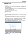
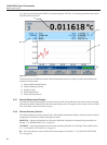
Main Menu
5.7.1.2.1 SET UP Rs (F1)
MAIN MENU | CHANNEL SETUP | CHANNEL SETTINGS |
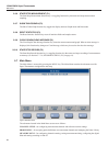
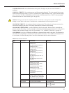
Pressing the Set Up Rs function key displays the Rs denition assigned to each Rs input. The Up/Down arrow
keys are used to scroll through the list to select an Rs input for conguration. The following function keys al-
low the user to congure the Rs input.
5.7.1.2.1.1 ASSIGN RESISTOR (F1)
MAIN MENU | CHANNEL SETUP | CHANNEL SETTINGS | SET UP Rs |
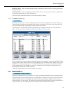
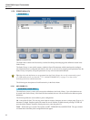
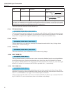
The Assign Resistor function key opens the resistor denition library. This is a list of Rs congurations that
have been created by the user. The resistor denition library may contain up to 50 resistor denitions. Every
denition in the library must have a unique ID.
Also displayed in the resistor denition library, at the end of the list, are factory default options VARIABLE
RESISTANCE and NO RESISTOR.
The VARIABLE RESISTANCE option is used when the Rs resistance will vary such as when a SPRT is being
used as a reference resistor. When in this mode, measurement output will be in ratio only.
If the NO RESISTOR option is chosen, the Rs Input cannot be used as a reference resistor connection.
5.7.1.2.1.1.1 DEFINE RESISTOR (F2)
MAIN MENU | CHANNEL SETUP | CHANNEL SETTINGS | SET UP Rs |
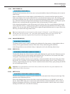
The Dene Resistor function key displays the resistor denition library. The displayed function keys are used
to create new Rs resistor denitions or edit denitions stored in the resistor denition library. The following
describe each function key.
5.7.1.2.1.1.2 ADD RESISTOR (F1)
MAIN MENU | CHANNEL SETUP | CHANNEL SETTINGS | SET UP Rs | DEFINE RESISTOR |
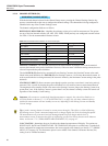
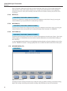
The Add Resistor screen is used to create a new Rs denition using the following conguration elds and
function key.
RESISTOR ID - used to identify the reference resistor. Pressing the ENTER key while the RESISTOR ID
eld is highlighted will open the Alpha-Numeric Interface to allow entry of a unique ID.
RESISTANCE VALUE - the resistance value of the Rs reference resistor. This resistance value is used to
calculate UUT resistance so it is important that it is entered correctly.
MAXIMUM CURRENT - establishes the maximum current allowed to be applied during measurement. This
prevents excessive current from being applied to the reference resistor.
CALIBRATION DATE - used to dene when the reference resistor was calibrated. If not used, the digits can
all be set to zeros.
DUE DATE - used to alert the user when the reference resistor is due for calibration. This is only applicable if
Rs DUE ALERT is enabled in the User Settings screen, see Section 5.7.4.1, USER SETTINGS (F1), on page
47.
SAVE (F1)
The Save function key saves the settings.
CANCEL (F5)
The Cancel function key exits Add Resistor without saving changes.