


35
Menus and Screens
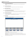
Main Menu
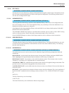
CALIBRATION DATE - the calibration date of the probe. The digits may be set to zero if the date is
undened.
NOMINAL CURRENT - the sensing current used for measuring the probe. The value entered is the current
used to measure the probe when 1 x Power is selected in the Channel Settings screen. Typical current settings
are 1.0 mA for a 25.5 Ω or 100 Ω PRTs and 0.010 mA for 10 kΩ thermistors (see “Table 13 Recommended
Reference Resistor for Various Probe Types” on page 30).
Caution: Sensing current must be carefully selected. Current that is too high can overheat and possibly
damage a sensor. Refer to the sensor’s manufacturer recommendations when setting the current.
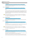
MAXIMUM CURRENT - the maximum allowed sensing current. This setting is used to prevent excessive
current from damaging the sensor. This setting supersedes the Nominal Current setting.
MAXIMUM TEMPERATURE - sets the temperature limit for the probe. When a probe’s measured tem-
perature exceeds this setting, a warning message is indicated on the Measurement screen and an audio alarm is
sounded if the Alert Beep setting is set to ON (see Section 5.7.4.1, USER SETTINGS (F1), on page 47).
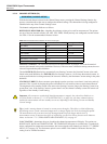
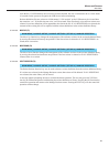
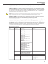
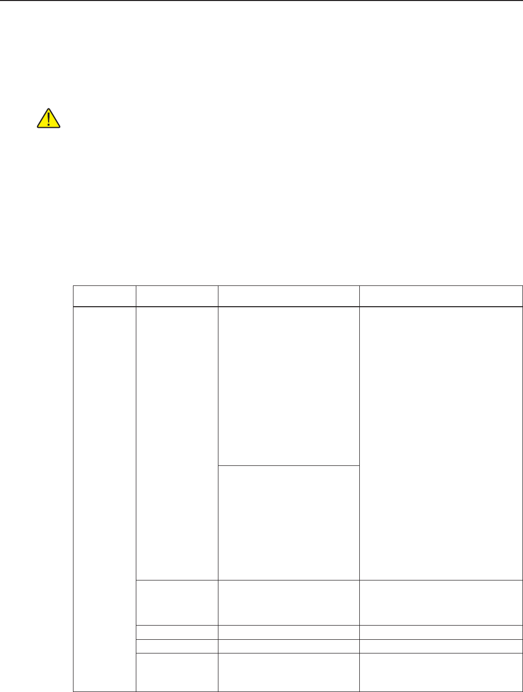
CONVERSION - the type of calibration coefcients or characterization used for the probe. The characteriza-
tion denes how temperature is calculated for a probe. When conversion is set to NONE, measurements will
be in resistance. See the following Probe Conversion Information table for more information.
Table 14 Probe Conversion Information
Type Conversion Coefficients Equations
PRT ITS-90 High Subrange 5 (-38 to 29 °C)
RTPW,a5, b5
High Subrange 6 (0 to 962 °C)
RTPW,a6, b6, c6, d
High Subrange 7 (0 to 660 °C)
RTPW,a7, b7, c7
High Subrange 8 (0 to 420 °C)
RTPW,a8, b8
High Subrange 9 (0 to 232 °C)
RTPW,a9, b9
High Subrange 10 (0 to 157 °C)
RTPW,a10
High Subrange 11 (0 to 30 °C)
RTPW,a11
See ITS-90 literature
Low Subrange 1 (13 to 273 K)
RTPW,a1, b1,c1,c2,c3
Low Subrange 2 (24 to 273 K)
RTPW,a2, b2,c1,c2,c3
Low Subrange 3 (54 to 273 K)
RTPW,a3, b3,c1,c2,c3
Low Subrange 4 (-189 to 0 °C)
RTPW,a4, b4
Low Subrange 5 (-38 to 0 °C)
RTPW,a5,b5
PT-100 R0
Use R0 = 100.0 for standard IEC-
751, ASTM-E-1137 or enter actual
probe R0 for improved accuracy
See IEC-751 or ASTM-E-1137 literature
CVD-ABC R0, A, B, C See CVD literature
CVD-ALPHA R0, ALPHA, DELTA, BETA See CVD literature
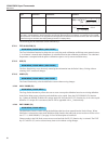
POLYNOMIAL C0, C1,….C7
tC
R
i
i
i
[]
[]
°C =
=
∑
0
7
Ω