15
Preparation for Operation
Line Voltage and Fuses
3 Preparation for Operation
3.1 Unpacking and Inspection
The Super-Thermometer is shipped in a container designed to prevent damage during shipping. Inspect the
contents of the container for damage and immediately report any damage to the shipping company. Instruc-
tions for inspection are included in the shipping container.
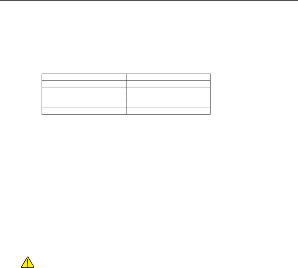
Table 9 Optional Accessories
Item Model or part number
Rack Mount Kit 1594-RMKT
2590 Scanner 2590
Case 1594-CASE
Carry-handle Kit 1594-HNDL
Extended range test report 1994 (1594A), 1995 (1595A)
3.2 Instruction Manuals
The Super-Thermometer instruction manual set is shipped on DVD. The set includes:
●
1594A/1595A Super-Thermometer User’s Guide
●
1594A/1595A Super-Thermometer Technical Guide
The 1594A/1595A Super-Thermometer User’s Guide contains instructions for unpacking and setting up the
instrument. Specications and an overview of Super-Thermometer operation are also included. The User’s
Guide is available in the following languages: English, Chinese, Spanish, Japanese, German, French, and
Russian.
The 1594A/1595A Super-Thermometer Technical Guide contains complete information for setting up and
operating the Super-Thermometer. It also includes instructions for remote operation, calibration and mainte-
nance. The Technical Guide is available in English only.
For ordering a replacement instruction manual DVD contact your local Fluke representative or service center.
All manuals are available online for download in PDF format.
3.3 Line Voltage and Fuses
CAUTION: To prevent possible damage to the instrument, verify the correct fuse is installed for the
selected line voltage setting.
The correct line power fuse and line voltage range was installed at the factory per the conguration that was
ordered. However, it is important to verify the correct fuse value and line voltage setting. The fuse is accessi-
ble on the rear panel in the PEM (Power Entry Module). The line voltage setting is shown in the PEM window
(see Figure 1 on page 16) and see Section 2.2, Specications, on page 5 for the fuse rating.
To check or replace the fuse and to verify or change the line voltage setting, refer to Figure 1 on page 16
and proceed as follows:


