


5-1
5. Configuring Local Alarms
5.1 Introduction
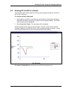
The CN8-SW system can use the Omega Plus Protocol to read the alarm state of any
controller that supports the protocol. Therefore, if an Omega Plus controllerÕs alarm
parameters have been configured and the controller has detected an alarm condition, the
A1 or A2 indicator on the controllerÕs Òfront panelÓ on the CN8-SW main display will
appear to be lit (red), matching the behavior of the A1 and A2 indicators on the controller
faceplate. The process value on the CN8-SW graphic display will also change color from
magenta (normal) to red (alarm). Controller alarm parameter values can be changed
using the CN8-SW software using the procedure described in Section 7.
As a bonus, the CN8-SW supports Òlocal alarmsÓ. These two process alarms can be
configured in CN8-SW for each controller on the network, including controllers that do not
provide an alarm function of their own, and controllers that support the original Omega
Protocol.
9
If a controllerÕs PV exceeds (high alarm) or falls below (low alarm) the
configured local alarm limit, the alarm indicators on the main display will ÒlightÓ and the
PV will change to red. Local alarms are configured using the procedure described
below.
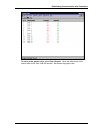
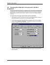
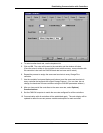
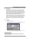
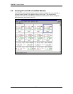
5.2 Procedure
To configure local process alarms:
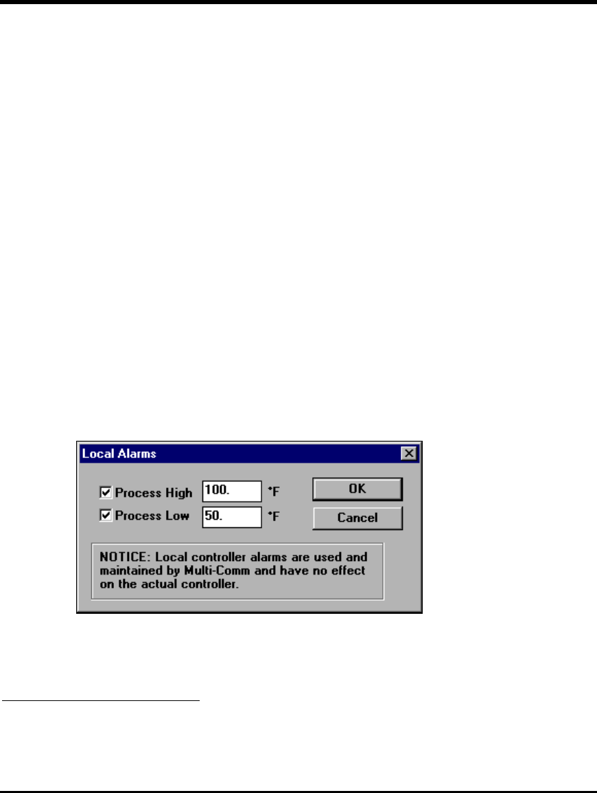
1. While logged in as MULTI (or another user with Controller Configuration privileges),
select Controller | Alarms. The Local Alarms window will open.
2. To enable local process alarm 1 (signaled using the controller imageÕs A1 indicator
on the main display), click on the box to the left of Process High.
9
Although some controllers that support the original Omega Protocol do provide parameters for
configuration of controller alarms (such as the Series 16 controlers), their alarm status cannot be read
using the original Omega protocol.