


Installation, Operation, and Maintenance Manual # 509252 Rev R 53
F300S Relay Coil Resistor Assembly Installation
The relay coil resistor assembly must be used if the line voltage and frequency used
with a P300M/P300MQ/P300MT power supply is 230-240 VAC at 50 Hz (nominal
voltage). These resistor assemblies prevent the premature failure of the relay coils in
high line voltage environments. There are two coil resistor assemblies available in a
retrofit kit (See Appendix E, “Replacement Parts”). One assembly is placed in series
with each of the coils of K101 and K102 in the power supply. These resistors should
also be used when it becomes necessary to configure the system for a line voltage and
frequency of greater than 230 VAC at 50 Hz (nominal voltage.)
Installation Instructions
1. Turn off the power and disconnect power from the power supply.
2. Remove the six cover screws and cover from the P300M/P300MQ power
supply. (Remove the four cover screws and cover from the P300MT power
supply.)
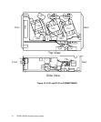
3. Locate relays K101 and K102. K101 is closer to the rear of the power supply
and K102 is closer to the front (refer to Figure 15 on page 54).
4. On K102, locate tab 0. A black wire with a pink-insulated terminal will be
connected to it.
5. Disconnect the black wire and press the pink-insulated female terminal of one
resistor assembly onto K102 relay tab 0.
6. Connect the black wire with the red-insulated terminal to the red male terminal
of the resistor assembly. The leads of the resistor assembly should be bent to
form a U shape to make this connection easier.
7. On K101, locate tab 1. Two black wires with pink-insulated terminals will be
connected to it.
8. Disconnect the black wire with the fully insulated right-angle terminal and leave
the double terminal with the pink insulation connected. Press the female terminal
of the remaining resistor assembly onto the exposed tab of the double terminal.
9. Connect the right-angle terminal to the male terminal of the resistor assembly.
The leads of the resistor assembly should be bent to form a Z shape to make this
connection easier.