


20 F300S/F300SQ Ultraviolet Lamp System
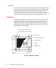
Mounting
The lamps can be mounted over a moving substrate or web, supported by the bottom
rails. The lamps should be mounted so that the rails sit 53 mm (2.1") above the surface
to be cured. This allows the elliptical reflector to focus the most intense strip of light
very near the substrate.
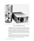
Power Supply
Each lamp system has its own power supply to house the high voltage circuits
necessary to energize the magnetron, as well as all control and interlock electronics,
and the built-in cooling fan.
The power supply is fully modular. Up to six units may be interconnected and
controlled from a single master unit. Any power supply may assume either Master or
Slave status in a multi-unit installation.
P300M/P300MQ/P300MT
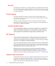
The power supply high voltage circuit consists of a dual half-wave voltage doubler
circuit which supplies a regulated source of high voltage power (approximately
3900V, 700 mA DC) to the magnetron in the irradiator. The capacitors and diodes
provide regulation and rectification to the high voltage transformer outputs.
RF Detector
The system includes a detection device which shuts the system down if microwave
energy in excess of permissible levels is in danger of being released into the work
environment. This might be caused by a faulty RF screen or some other type of damage
to the lamp, or by inadequate or damaged shielding.
The power supply fault detection circuitry searches the system for a functioning RF
detector by means of the System Interconnections Bus. A multi-unit installation must
have at least one RF detector, which is usually connected to the master power supply.
Additional detectors may be connected to slave units.
During the startup sequence, each power supply will automatically perform a
functional test on any installed RF detector (if switch S1-5 is set to “YES”). The
operator may also verify detector operation by pushing a test button on the RF-1
module for 4 seconds. Complete information appears in Chapter 5, “Troubleshooting”.
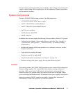
System Interconnections
All electrical connections to the power supply are made through connectors at the rear.
Instructions for wiring are provided in Chapter 3, “Electrical System”. The power
supply does not require any routine maintenance other than occasional cleaning of the
interior with compressed air (depending on the environment).