


Installation, Operation, and Maintenance Manual # 509252 Rev R 51
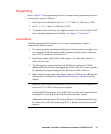
North American Applications: 3x12 AWG UL listed
International Applications: 3x2.5 mm
2
Harmonized, VDE
Both cable types should have minimum ratings of 16A, 300V, 0-60 °C.
Refer to Table 11 on page 57 in Chapter 4, “Operation,” for the leg currents for each
power supply/voltage combination.
Frequency Tapping of HV Capacitors
If it becomes necessary to configure the system for a line frequency other than that
delivered, the following steps should be followed:
1. Turn the unit POWER switch OFF and unplug the power cord.
2. Remove the power supply cover (six screws).
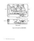
3. Locate the HV capacitors C101 and C102 (refer to Figure 15 on page 54).
4. Discharge the capacitor by shorting the capacitor terminals with an insulated
screwdriver.
5. Locate the jumper connected to the T terminal of each capacitor.
6. Disconnect the opposite end of this jumper from the capacitor terminal to which
it is connected, and reconnect it to the appropriate terminal for the desired line
frequency (50 for 50 Hz, 60 for 60 Hz).
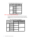
QRO HV Capacitors (For QRO only)
When the Quick Restart Option is installed, one element of the retrofit is the
replacement of the HV capacitors. These HV capacitors are a different value than the
standard HV capacitors, but the frequency tapping procedure is exactly the same.
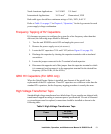
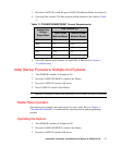
High Voltage Transformer Taps
Standard high voltage transformers have labeled taps. Power supplies are shipped with
transformers tapped according to customer power specifications. If a unit is relocated
or a transformer must be replaced, connections should be installed as shown in the
following table.
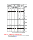
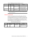
Table 9. High Voltage Transformer Taps
Power
HV Plate
Transformer
Primary Tap