


Installation, Operation, and Maintenance Manual # 509252 Rev R 49
Programming
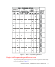
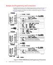
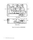
Refer to Figure 11 for programming switch S1 settings and set programming switches
of each power supply as follows:
1. Select one unit as the Master. Set S1-1, 1-2, 1-3 and 1-5 of this unit to YES.
2. Set S1-1, 1-2, 1-3, and 1-5 of all slaves to NO.
3. To shut down all units in case of a single-unit fault, set S1-4 on all units to YES
(For a detailed explanation of unit faults, see Chapter 4, “Operation.”)
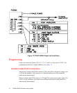
Connections
The following procedure describes how to connect multiple power supplies
(master/slave) within a system.
1. For proper operation, including fault detection, connect each power supply to the
next using the H760 interconnect cables supplied with the system. Cables run
from J107 of one unit to J106 of the next.
2. Install input/output plugs P105A (with jumpers - provided with system) in
J105A of slave units.
3. The Master power supply must have an RF Detector connected to J105A;
additional RF detectors may be plugged into J105A of the Slave power supplies
by replacing the jumpered plug with the RF detector cable connector.
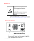
4. Make interlock connections to the Master using the P105A plug on RF detector
cable harness as indicated in “Input/Output Connections” on page 45 in this
chapter.
NOTES: When installing additional RF detectors on slave power supplies, be
sure to set S1-5 to YES on those power supplies.
If additional RF detectors are used, an RF fault in a slave will automatically be
interpreted as a system fault; this will shut down the entire system.
Additional interlocks such as RF, Remote Blower, and External Interlock may
be connected to a SLAVE unit through P105A. Remove any factory-installed
jumpers.