


Installation, Operation, and Maintenance Manual # 509252 Rev R 41
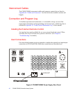
1. Disassemble the strain relief housing by removing the retaining screws and
unscrewing the housing from the connector body.
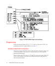
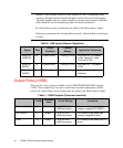
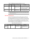
2. To connect EXT INTLK or SYS BLWR inputs, remove jumper wires and the
attached pins as indicated in Table 5, Table 6, and Table 7 in this chapter.
3. With a crimping tool, attach wires from user devices to new pins (supplied with
system) and insert the pins in the proper locations.
4. Reassemble the strain relief housing.
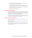
Power Supply Programming
P300M/P300MQ/P300MT power supplies may be interconnected to form a complete
system of up to six lamps. Through use of the System Interconnections Bus control
functions, the entire system may be operated by the lamp control switch of one master
power supply, or by a switch on an external control panel.
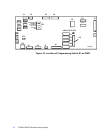
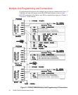
See Figure 10 on page 42 for the location of programming switch S1. To access S1,
remove the six screws on the side of the power supply cover. For programming switch
S1 settings, see the table illustration in Figure 11 on page 43.
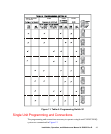
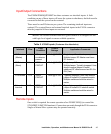
Settings for Six-Position Switch S1
Positions 1, 2, and 3 of S1 (see Figure 10) must be set to determine whether a power
supply is a master or a slave.
Position 4 determines whether a unit fault will turn off all power supplies or only the
unit where the fault occurs.
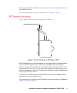
Position 5 indicates to the system bus whether a power supply (either the master or a
slave) has an RF Detector connected to it. (There must be at least one RF Detector
connected to a system.)