


Theory of Operation
6–10
760A / 760D / 760N
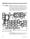
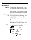
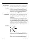
CR4 is the high voltage rectifier. Filter capacitors C3, C4, and C8 work with
CR4 to provide –2530 V to the CRT cathode. U1 is a four-times multiplier
providing +11 kV to the CRT anode.
Q1 and Q2 form an operational amplifier that sets the voltage at the bottom of
the focus divider. The front-panel FOCUS pot determines the voltage at the
bottom of the focus divider. The Center Focus control, R11, is set for optimum
beam focus, as viewed on the CRT, with the front-panel FOCUS control set to
mid range. Once the Center Focus adjustment has been set, adjusting the
front-panel FOCUS control changes the voltage at the bottom end of the divider
and, consequently, the voltage on the CRT focus anode.
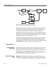
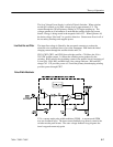
The cathode of the CRT is at a –2750 V potential with the grid coupled to the
Z-Axis Amplifier by the Grid Drive circuit. The grid is approximately 75 V
negative with respect to the cathode. The 200 V
p-p
sine wave present at the
cathode of CR8 is input to the Grid Drive circuit where it is clipped for use as
CRT control grid bias.
The sine wave from the cathode of CR8 is coupled through R47 to a clipping
circuit consisting of CR5 and CR6. Clipping level for the positive excursion of
the sine wave is set by the CRT Bias adjustment, R58. The negative clipping
level is set by the front-panel INTENSITY control through the Z-Axis Amplifier.
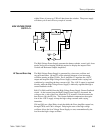
The clipped sine wave is coupled through C11 to a rectifier made up of CR1 and
CR3. The rectified, clipped sine wave is the CRT control grid bias voltage. C9
couples the blanking signal from the Z-Axis Amplifier to the CRT control grid.
DS1 and DS2 limit the CRT grid to cathode voltage at instrument turn on or off.
DS3 limits the CRT heater to cathode voltage.
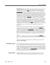
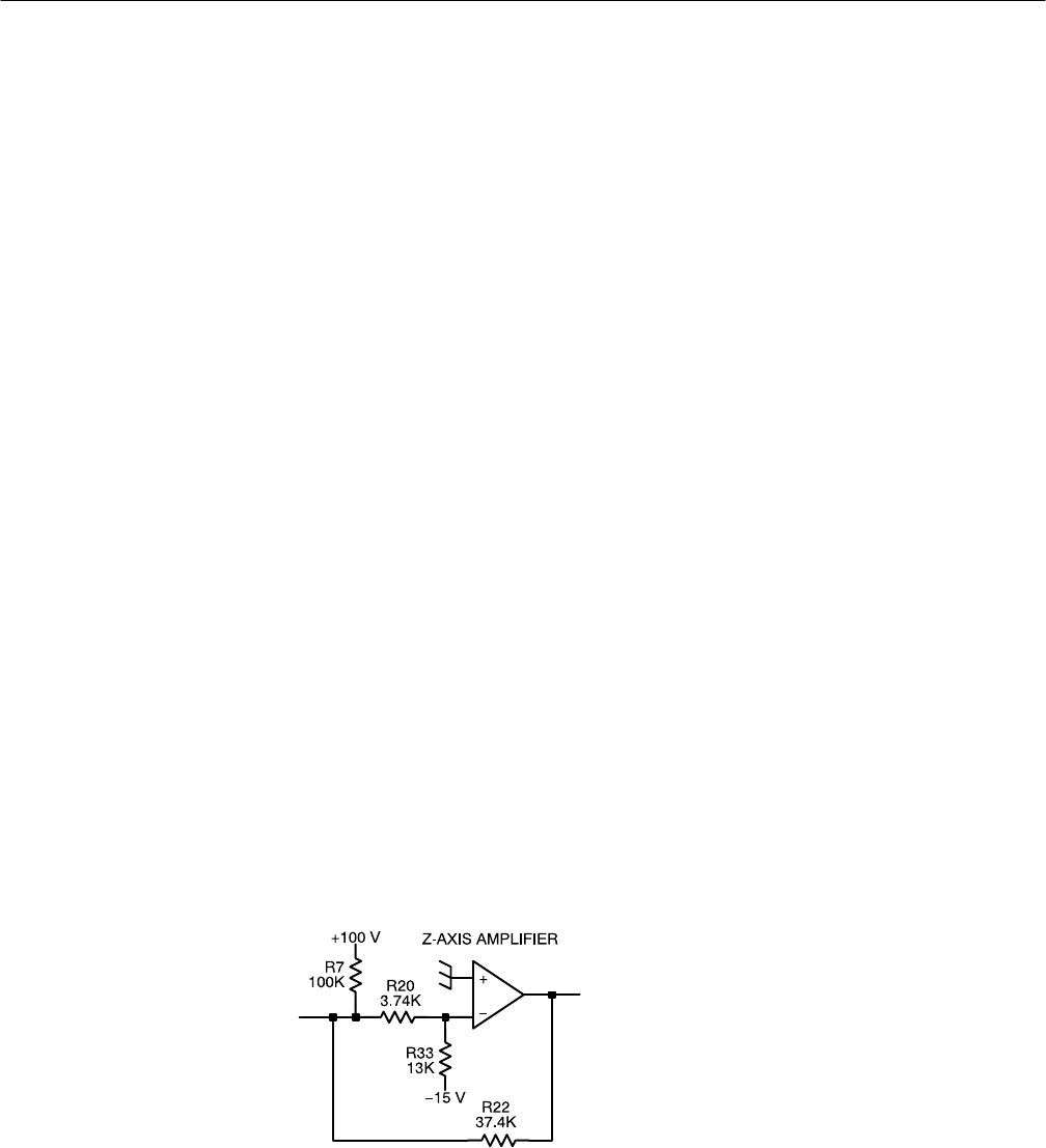
This is an inverting amplifier with negative feedback. R22 is the feedback
resistor while R7, R20, and R33 act to maintain the summing junction at +5 V.
Without any Z-Axis input current, the amplifier output is approximately +10 V.
Negative Z-Axis input current will cause the output to go positive.
Q5 is a current amplifier feeding the output stage. Q3 and Q4 form a push-pull
output stage. Q3 acts as a 2.7 mA constant current pull-up, while Q4 is the
Power Supply Outputs
Focus Amplifier
Grid Drive Circuit
Z-Axis Amplifier