


Installation
3–2
760A / 760D / 760N
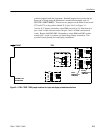
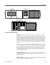
To enable the 760A bar graph to indicate 0 dB with an input of 0, +4, +8, +12, or
+16 dBm, move the jumpers on J185 (LEFT), J385 (RIGHT) and J657 (AUX-
ILIARY) to the desired sensitivity, which is marked on the Main circuit board
(Assembly A3) at each jumper location. Figure 3–3 shows all jumper locations
on the Main board and what each jumper position represents.
NOTE. The specified level is that of a sine wave which reads 0 dB peak program
level, not the line–up level. For a ppm, line–up level is 8 dB below peak
program level. This means that if the house level is +4 dBu (the level that
indicates 0 on a VU meter), then the 760A sensitivity jumper should be set 8 dB
higher, or +12 dBu. The line–up tone should then read 8 dB. See the discussion
about ppm vs. VU meters under Level Setups in Section 2.
A User–definable jumper position is provided for installations that use a
reference level other than 0, +4, +8, +12, or +16 dBm. The following para-
graphs explain the procedure for selecting the proper resistor value so any input
level will indicate 0 dB on the bars.
User–definable resistors may be installed at R183 (LEFT), R383 (RIGHT), and
R658 (AUXILIARY) if the standard range of input sensitivities previously listed
does not fit your needs. These resistor positions are already used in the 760D
and 760N. The following formula can be used to determine the value of resistors
needed to achieve a 0 dB indication with your reference level:
R
SET
=
20K
7.962
10
G/20
–1
where R
SET
is the user–definable resistor value and G is the desired reference
level in dBu.
Once the resistor value is determined and resistors are installed at R183, R383,
and R658, move the jumpers on J385, J185, and J657 to the ”U” position. This
is the factory set jumper position for the 760D and 760N.
The 760A is set at the factory for Infinite input termination, with 600 or 150
termination being jumper selectable. The position of the jumper on J192
(LEFT), J292 (RIGHT), or J664 (AUXILIARY) determines the input termination
for that channel. The Main circuit board is marked at the jumper location to
indicate the termination value that each jumper position represents. See
Figure 3–1.
The 760A CRT display can be changed from the factory set ”sound stage”
orientation (where L=R is vertical) to a standard X–Y orientation (where Left is
vertical). To accomplish this change, you must install the optional external
User–Definable Input
Sensitivity (Standard 760A
only)
Changing Input
Termination
Changing Display
Orientation